
User`s guide


Agilent PXT Wireless Communications Test Set
User’s Guide
152
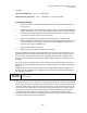
Typical UL Maximum Performance Setup and Expected Bit Rate (TDD)
Channel Bandwidth = 20MHz (TDD)
UL Resource Blocks
UL I_MCS
UL-DL Configuration
Expected UL Mbps (TDD)
100
22
1
18.72 Mbps
100
22
2
9.36 Mbps
100
22
5
4.68 Mbps
100
22
6
23.444 Mbps
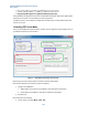
The PXT is now configured for maximum bi-directional bitrates.
Next we’ll look at driving the E2E data through the PXT E2E link to achieve maximum bitrates.
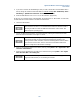
Driving E2E throughput using Iperf
Driving the E2E data throughput using a tool like Iperf is ideal. It is easy to use and it allows for UDP/TCP
stream(s) to be sent at the desired rates as well as reporting the bitrate.
Running UDP streams with a server running at the receive side reports bitrate achieved, packet loss %,
latency, jitter, and out of order packets. TCP streams simply report the current bitrate achieved hiding the
loss/jitter statistics.
UDP tests should be performed prior to any TCP benchmark tests as UDP reports the quality of the IP link.
This helps identify any IP link issues first. If the IP link suffers loss of around 1% or more (for example: from
an incorrect attenuation level setup on the PXT), TCP bitrate tests will be seriously reduced due to
retransmissions.
Iperf running TCP test streams automatically adjusts the bitrate to the maximum that is achievable. UDP
test streams require a bitrate specified (defaults to 1Mbps).
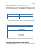
Typical Iperf IPv4 UDP Command Usage
Uplink
PXT server (192.168.1.230) > iperf –s –i1 –p5050 –w300k –u
UE Host Client PC (192.168.1.51) > iperf –c 192.168.1.230 –i1 –w300k –u –b48m –t300 –p5050
Downlink
UE Host Client PC (192.168.1.51 > iperf –s –i1 –p5052 –w300k –u
PXT server (192.168.1.230) > iperf –c 192.168.1.51 –i1 –w300k –u –b102m –t300 –p5052
Typical Iperf IPv4 TCP Command Usage
Uplink
PXT server (192.168.1.230) > iperf –s –i1 –p5050 –w20m
UE Host Client PC (192.168.1.51) > iperf –c 192.168.1.230 –i1 –w20m –t300 –p5050