
User`s guide


Agilent PXT Wireless Communications Test Set
User’s Guide
150
Example PXT Configuration for Maximum E2E Throughput Testing
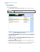
1. Pre-set PXT
2. Load Default Scenario file “FDD_Combined_v6.3” or custom scenario file.
3. Set the following parameters:
a. CH Bandwidth = 20MHz
b. EPC = Embed
c. RRC No. of Antennas = 2
d. RRC Transmission Mode = TM3 or TM4
e. Attenuation = Adaptive
f. Frequency Band = <UE band>
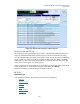
4. Set PHY UL Resource Allocation Mode = Fixed MAC Padding or Auto. (NOTE: TCP or TDD E2E
streams require that uplink Fixed MAC Padding be configured to allow fast return of TCP ACK’s).
5. Set PHY DL Resource Allocation Mode = Auto. (Note: PHY DL Resource Allocation must always
be set to Auto for E2E tests.)
6. Set PHY DL Subframe#5 Control = Max Th or Default (Use Max Th
to achieve maximum bitrate
benchmark results, or Default
for long term tests greater than 3 hours.)
7. Set PHY CFI = 1
(For TDD, set CFI (Special SF) = 1)
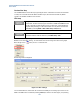
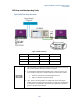
8. Ensure the E2E Test Station is present on the network at the PXT’s Default Gateway.
9. Connect the UE.
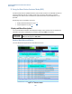
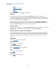
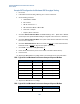
10. Adjust the DL MCS/RB sizes accordingly based on the information shown in the table below:
FDD - Typical DL Cat3 Maximum Performance Setup and Expected Bit Rate
DL Resource Blocks
DL I_MCS
Expected Mbps (FDD)
68 (68-69)
28
102.048 Mbps
80 (79-81)
27
102.048 Mbps
84 (82-84)
26
102.048 Mbps
88 (87-90)
25
102.048 Mbps
94 (93-96) 24 102.048 Mbps
100 (0x01FFFFFF bitmap)
23
102.048 Mbps
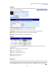
11. Adjust the UL MCS/RB sizes accordingly:
FDD - Typical UL Cat3 Maximum Performance Setup and Expected Bit Rate
UL Resource Blocks
UL I_MCS
Expected Mbps (FDD)
100
23
51 Mbps