
User`s guide


Getting Started 2
E6651A User’s Guide 19
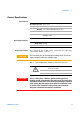
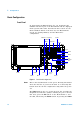
Rear Panel
Figure 3 The E6651A Test Set Rear Panel
Power Switch This switch must be ‘ON’ to enable switching the Test Set on
and off using the Front Panel On/Off switch.
Power Connector: Connect the AC power cable here.
Reference clock
Port
Use the 10 MHz Clock Port to synchronize all system clocks
of the Test Set with the Device Under Test (DUT). Use the
Output Port if you want to supply the DUT with the Test
Set's clock. Use the Input Port if you want to provide the
DUT's clock to the Test Set.
Trigger Ports Use the Trigger Port to synchronize the WiMAX TDD frame
of the Test Set with the DUT. Use the Output Port if you
want to apply the synchronization signal from the Test Set
to the DUT. Use the Input Port if you want to apply the
signal from the DUT to the Test Set. Trigger #2 ports are
used to provide downlink and uplink transition information.