
User`s guide


Getting Started 2
E6651A User’s Guide 17
button does not turn the power off, hold the button down
for 5 seconds to bypass the operating system termination,
and power off.
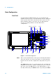
LCD Screen Measurement results are displayed on the LCD Screen.
Different screen layouts are used for each mode of operation.
In each layout, the screen is divided into three areas: the
Setting Window, the Working Window, and the Selection
Menu.
Menu Press the Menu button to display the top level menu for the
current Measurement Window.
Return Press the Return button to display the previous menu for the
current Measurement Window.
More Use this button to select additional options when more than
6 menu options are available.
Knob Increments and decrements the value of the currently
selected parameter.
USB Port The Test Set software runs on an embedded operating
system. Devices using a USB interface may be connected to
this port.
Arrow Key Move the on- screen cursor using the Left and Right Arrow
Keys.
Numeric and Hex
Keys
Parameters like frequency can be input using these keys.
Hexadecimal values can be input using the Hexadecimal
Keys.
RF I/O An antenna or cable is connected to this port for
communication with the subscriber station. This port can act
as an RF input port, an RF output port or a duplex port
based on the mode of operation. In BSE mode, this port
automatically switches between input and output based on
the downlink and uplink frame duration. In SA mode, this
port may operate as an RF input or duplex port.
Menu Selection
Keys
Six buttons are available on the right hand side of the LCD
Screen for menu selection. The current menu is displayed at
the right side of the screen. When more than 6 menu
options are available, select More to see the additional
options.
Amplitude Adjust values related to input power using this button,
including Amplitude, Attenuation, Reference Level, Scale and
Amplitude Offset.