
Technical data


Front and Rear Panel Features 2
Getting Started Guide 43
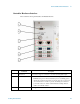
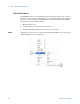
TRX Module Hardware Interface
There can be as many as four TRX modules in the PXI rack; each has the same hardware
interface, as illustrated below.
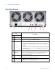
Item
Description
# Name
1TRXn STATUS When line power is applied to the PXI chassis, the STATUS LED for each TRX
module lights orange to indicate that hardware is ready but the software is still
booting up. After bootup the LED lights green to indicate that both hardware and
software are ready. Blinking green indicates that software is processing a request.
2 RFIO 2 This Type N connector is a full-duplex RF input/output port.
3 RFIO 1 This Type N connector is a full-duplex RF input/output port.
4 TRIG OUT 2 A trigger output used to synchronize other test equipment with the test set.
Configurable from the Input/Output keys.
5 TRIG IN I A trigger input used to synchronize other test equipment with the test set.
Configurable from the Input/Output keys.
6 RF4 I/O This Type N connector is a half-duplex RF port which can be configured as an
input or an output.