
Technical data

74 Chapter 5
Mode Parameters
Test Set Parameters
Mode Parameters
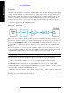
Corrections
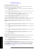
Amplitude corrections can be applied to the output and input ports of the test set when the selected mode
is Sequence Analyzer. The Amplitude Corrections arrays can be entered by the user, sent over SCPI, or
loaded from a file. The purpose of the corrections is to compensate for losses in signal paths external to
the test set. For example, if you have a test system with frequency-dependant path losses due to cable,
amplifier or attenuator non-linearities (as in the path illustrated below), and you can quantify the
frequency-related variations, you can apply a frequency-dependent correction to the test set analyzer
input. In this way the signal appearing at the test set’s input port can appear to have the same spectral
content as the signal leaving the transmitting device.
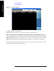
Figure 5-2. Corrections
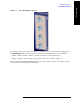
The corrections are applied as a table of x and y parameters, with the x specifying the frequency and y
specifying the amplitude correction to be applied at the frequency, x. To enter corrections from the front
panel, use the
Input/Output hardkey and select Corrections. For detailed information on how to enter
correction data, see the Sequence Analyzer online help (or in pdf format, the User’s and Programmer’s
Reference).
The test set supports up to six sets of correction data. One of these sets (or any combination of the six
sets) can be applied to an RF port. In the case of an
RF I/O port which is being used as an input and an
output simultaneously, a correction data set can be applied to the input, the output, or both.
NOTE The same correction data set cannot be applied to more than one port.
The remote control command to apply one of the sets of corrections to a port are as follows:
[:SENSe]:CORRection:CSET[1]|2|3|4|5|6:RF:PORT RF|RFIO1|RFIO2|RFOut
The CSET parameter selects the set of corrections to apply (the sets are identified by numbers 1 to 6) and
the RF:PORT parameter selects the port. To apply multiple corrections to a port, send the SCPI
command multiple times with the appropriate CSET number selected. For example, to set the corrections
in correction files 1, 2 and 4 to the RF Output port send:
:CORR:CSET1:RF:PORT RFOut; :CORR:CSET2:RF:PORT RFOut; :CORR:CSET4:RF:PORT RFOut
For detailed information on how to enter correction data, see the Sequence Analyzer online help (or in
pdf format, the User’s and Programmer’s Reference).