
Technical data


276 Chapter 18
LTE-TDD Programming Commands
Power vs. Time (PvT)
LTE-TDD Programming Commands
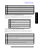
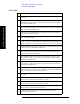
PvT results
Index Result Parameter
0 Overall Pass/Fail Result shows the mask test result (0.0 = pass, 1.0 = fail, -1.0:
Not tested)
1 Ramp Up Time Pass/Fail Result shows ramp up time limit test result. The time
mask defines the ramping up time allowed for the UE between transmit OFF
power and transmit ON power.
2 Ramp Down Time Pass/Fail Result shows ramp down time limit test result. The
time mask defines the ramping down time allowed for the UE between transmit
ON power and transmit OFF power.
3 Off Power Before Pass/Fail Result shows uplink transmit off power limit test
result which occurs before the burst.
4 Off Power After Pass/Fail Result show uplink transmit off power limit test result
which occurs after the burst.
5 On Power/Mean Power Result is the mean power (in dBm) of the active part in
the range specified by Analysis Time Slot and Measured Time Slots in the most
recently acquired data, or in the last data acquired at the end of a set of average.
6 Burst Width Result is the width of continuous active slots in the range specified
by Analysis Time slot and Measured Time Slots.
7 Trigger Diff Result is the time difference between the position of the trigger line
and the start point of the detected burst. (This result is NaN 9.91E+37 when
trigger is Video Trigger or Free Run.)
8 Ramp Up Time Result is the time difference between 10% and 90% voltage
points (relative to peak) on the positive slope of the burst, here burst has the
same meaning in Burst width.
9 Ramp Down Time Result is the time difference between 90% and 10% voltage
points (relative to peak) on the negative slope of the burst, here burst has the
same meaning in Burst width.
10 Off Power/Off Power Before Result is the mean power measured during the
transmitter OFF period, When Direction is Uplink, this result is the OFF power
during the sub-frame prior to the active sub-frame.
11 Off Power After Result is the OFF power during the sub-frame following the
active burst.
12 Maximum Power Result is maximum peak level in the range specified by
Analysis Time Slot and Measured Time Slots (in dBm).
13 Minimum Power Result is the minimum peak level in the range specified by
Analysis Time Slot and Measured Time Slots (in dBm).
14 Actual Sample Interval Result is a floating point number representing the time
between samples of uncompressed I/Q trace data.
15 Actual Number of Samples Result is the number of data points in the
uncompressed I/Q trace data.