
Technical data

160 Chapter 11
Example Test Scenarios
Verification Example
Example Test Scenarios
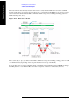
The waveform we have already created can be used to verify that the DUT can receive the downlink
signal, synchronize to it, and respond to it. However, to perform the actual ILPC test, we need to create a
second waveform which includes TPC commands which correspond to a falling and rising pattern of
DUT transmit power, as 2):
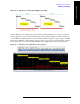
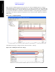
Figure 11-14. ILPC Power Profile
The “down” (0) or “up” (1) values for the TPC commands correspond to falling or rising power in 1 dB
or 2 dB increments (depending on the step size that has been set up on the DUT).
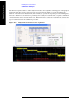
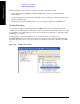
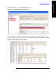
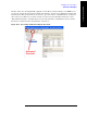
To create this series of down commands and up commands, in the Channel Setup for DPCH we change
the TPC pattern to “User Defined Bits” and enter a sequence of 90 zeroes followed by 90 ones.