
Technical data


150 Chapter 11
Example Test Scenarios
Calibration Example
Example Test Scenarios
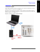
The maker of the mobile device has created an application for running the device from a controller; this
tool is used to configure, operate, and calibrate the DUT.
By means of this application, the DUT is commanded to transmit an uplink signal for a series of 16
channels (and to step through 5 power levels for each channel). The test set measures the 5 RF power
levels at each uplink frequency, so that this test data can be used to create calibration factors which are
stored in the DUT and later used to adjust its transmit level at different frequencies.
Because a frequency change cannot occur during an acquisition, the sequence needs to include 16
separate acquisitions (one for each channel). The 5 descending power levels which the DUT transmits on
each channel have a duration of 20 ms; therefore, a 100 ms interval needs to be set aside for each
channel. (However, the acquisitions will each be shortened to 95 ms, so that there is a brief gap to arm
the trigger for the next acquisition.)
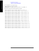
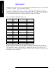
Table 11-1. Uplink and Downlink Frequencies
# Channel Uplink Freq Downlink Freq
1 1013 824.7 869.7
2 46 826.38 871.38
3 98 827.94 872.94
4 150 829.5 874.5
5 202 831.06 876.06
6 254 832.62 877.62
7 306 834.18 879.18
8 358 835.74 880.74
9 410 837.3 882.3
10 462 838.86 883.86
11 514 840.42 885.42
12 566 841.98 886.98
13 618 843.54 888.54
14 670 845.1 890.1
15 722 846.66 891.66
16 779 848.37 893.37