Agilent E6640A EXM Wireless Test Set V9065B Sequence Analyzer Measurement Guide Agilent Technologies
Notices © Agilent Technologies, Inc. 2009-2014 No part of this manual may be reproduced in any form or by any means (including electronic storage and retrieval or translation into a foreign language) without prior agreement and written consent from Agilent Technologies, Inc. as governed by United States and international copyright laws. Trademark Acknowledgements Microsoft® is a U.S. registered trademark of Microsoft Corporation. Windows® and MS Windows® are U.S.
Warranty This Agilent technologies instrument product is warranted against defects in material and workmanship for a period of one year from the date of shipment. During the warranty period, Agilent Technologies will, at its option, either repair or replace products that prove to be defective. For warranty service or repair, this product must be returned to a service facility designated by Agilent Technologies.
Contents 2. Analyzer List Sequencer Parameter Definitions Analyzer Sequence . . . . . . . . . . . . . . . . . . . . . . . . . . . . . . . . . . . . . . . . . . . . . . . . . . . . . . . . 22 Acquisition Parameters . . . . . . . . . . . . . . . . . . . . . . . . . . . . . . . . . . . . . . . . . . . . . . . . . . . . . 23 Analysis Interval Parameters . . . . . . . . . . . . . . . . . . . . . . . . . . . . . . . . . . . . . . . . . . . . . . . . 31 3.
Table of Contents Contents 9. Sequence Setup Commands Programming Analyzer Sequences (Combination Commands) . . . . . . . . . . . . . . . . . . . . .108 Programming Analyzer Sequences (Parameter-Specific Commands) . . . . . . . . . . . . . . . .111 Programming Source Sequences (Combination Command) . . . . . . . . . . . . . . . . . . . . . . . .130 Programming Source Sequences (Parameter-Specific Commands) . . . . . . . . . . . . . . . . . .132 10.Programming a Sequence Sequence Programming Example . . .
Contents 16.1xEV-DO Programming Commands Adjacent Channel Power (ACP) . . . . . . . . . . . . . . . . . . . . . . . . . . . . . . . . . . . . . . . . . . . . . 240 Spectrum Emissions Mask (SEM) . . . . . . . . . . . . . . . . . . . . . . . . . . . . . . . . . . . . . . . . . . . 243 Occupied Bandwidth (OBW) . . . . . . . . . . . . . . . . . . . . . . . . . . . . . . . . . . . . . . . . . . . . . . . 246 Modulation Accuracy (Rho) . . . . . . . . . . . . . . . . . . . . . . . . . . . . . . . . . . . . . . .
Table of Contents Contents Occupied Bandwidth (OBW) . . . . . . . . . . . . . . . . . . . . . . . . . . . . . . . . . . . . . . . . . . . . . . . .333 Modulation Accuracy (EVM & Spectral Flatness) . . . . . . . . . . . . . . . . . . . . . . . . . . . . . . .334 MIMO Modulation Accuracy (EVM) . . . . . . . . . . . . . . . . . . . . . . . . . . . . . . . . . . . . . . . . .
What is the Sequence Analyzer? 1 What is the Sequence Analyzer? This chapter provides a basic introduction to the Sequence Analyzer mode.
What is the Sequence Analyzer? What is the Sequence Analyzer? Sequence Analyzer Introduction Sequence Analyzer Introduction The Sequence Analyzer mode makes it possible to define, save, and execute a series of data acquisitions (controlled by the analyzer list sequencer) and/or a series of RF stimulus outputs (controlled by the source list sequencer). This defined series of acquisitions and/or outputs is known as a sequence.
Parameter definitions associated with the source and analyzer list sequencers are defined in Chapter 2 , “Analyzer List Sequencer Parameter Definitions,” on page 21 and Chapter 3 , “Source List Sequencer Parameter Definitions,” on page 35. NOTE The analyzer list sequencer uses measurements from other applications on the test set, and all licensing requirements apply to these applications when they are used in Sequence Analyzer mode.
What is the Sequence Analyzer? What is the Sequence Analyzer? Sequence Analyzer Introduction Analyzer List Sequencer The analyzer list sequencer provides a large amount of flexibility in the capture of an RF signal and the number of measurements that can be made. Because of this, there are many parameters that the user can set up to suit particular measurement requirements. The parameters are described in detail in Chapter 2 .
User-defined parameters for the sequence determine various important characteristics of the acquisitions (for example, the frequency of the acquired signal) and of the analysis intervals (for example, the type and timing of measurements). A sequence is saved as a file of tab-separated values representing sequence parameters. The parameters that are used by the analyzer list sequencer (rather than the source list sequencer) are placed in the file under the heading: ### Analyzer ###.
What is the Sequence Analyzer? What is the Sequence Analyzer? Sequence Analyzer Introduction Source List Sequencer The signal generator (on the source side of the test set) is used to produce RF stimulus waveforms for use in calibrating and testing mobile devices. The Source List Sequencer can be used to execute a series of stimulus operations, in either of two ways: • In the Sequence Analyzer mode, the source list sequencer is run by the same sequence which is also running the analyzer list sequencer.
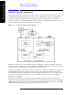
Example Sequence: Equally Spaced Analysis Intervals To help further clarify the concepts of sequences, acquisitions and analysis intervals, an example of a calibration sequence is shown in Figure 1-5. A spreadsheet is used to set up the sequence, acquisition and analysis interval parameters and subsequently generate a tab separated file which is loaded into the list sequencers. The use of the spreadsheet is defined in Chapter 7 but in this chapter it is used to help explain the Sequence Analyzer concepts.
What is the Sequence Analyzer? What is the Sequence Analyzer? Example Sequence: Equally Spaced Analysis Intervals Figure 1-6. Sequence Spreadsheet The first row of entries in the spreadsheet sets up the acquisition settings (as represented by the first 18 parameters in the row) for the first acquisition.
Example Sequence: Variable Analysis Intervals Figure 1-7 shows an example of a data sequence that has three bursts of data. Each burst is at a different frequency; therefore, three different acquisitions must set up in the analyzer list sequencer to capture this data. The associated spreadsheet is shown in Figure 1-8. Each acquisition starts at the burst trigger, because the Input Trigger Delay parameter has been set to zero for each acquisition.
What is the Sequence Analyzer? What is the Sequence Analyzer? Example Sequence: Variable Analysis Intervals which time the basic measurements of Transmit Power, Phase Error, Frequency Error, and IQ Data are made (Measurement Bitmap value 1111).
Sequence Setup There are a number of ways to set up a Sequence in the test set. The possibilities are described in these chapters: • Front panel setup - see Chapter 6 , “Front Panel Sequence Setup,” on page 77 • Spreadsheet setup - see Chapter 7 , “List Sequencer Spreadsheet Data Entry,” on page 91 • Remote setup - see Chapter 10 , “Programming a Sequence,” on page 137 for an example of how to write a program to set up a Sequence.
What is the Sequence Analyzer? What is the Sequence Analyzer? Sequence Setup 20 Chapter 1
2 Analyzer List Sequencer Parameter Definitions This chapter describes the parameters that are used in the setup of the analyzer list sequencer. (The analyzer and source list sequencers can exchange triggers, but are otherwise configured independently.
Analyzer List Sequencer Parameter Definitions Analyzer Sequence Analyzer Sequence In the case of the analyzer list sequencer, a sequence is defined as a series of one or more data acquisitions, each with its own set of measurements to be performed. A sequence is set up so that all the data needed for the calibration or verification of a device is acquired, and all the required measurement results are returned in the shortest time possible.
Analyzer List Sequencer Parameter Definitions Acquisition Parameters Acquisition Parameters Acquisitions, as successive steps in a sequence, make it possible to capture data which varies in frequency, in power range, and in other characteristics which may require changes to the configuration of the test set. This section describes the 14 parameters which configure the test set for a single acquisition.
Analyzer List Sequencer Parameter Definitions Acquisition Parameters The key path for selecting the Radio Standard from the front panel menus is: [Meas Setup], Acquisition Setup, Radio Setup, Radio Standard NOTE A particular radio standard will be available here only if the application for the associated measurement mode (GSM, for example) is currently loaded. 3: Radio Band This parameter specifies a radio band appropriate to the radio standard specified in the previous parameter.
Analyzer List Sequencer Parameter Definitions Acquisition Parameters 4: Device (for Channel) This parameter is used by the analyzer to determine the channel plan to be used when computing the Frequency/Channel values. The choices are BTS (Base Transceiver Station) and MS (Mobile Station). However, in the initial release of the EXM test set, measurements are supported only for mobile stations; therefore, MS should always be selected.
Analyzer List Sequencer Parameter Definitions Acquisition Parameters 8: Instrument Gain Type This parameter specifies one of three possible settings which control the input gain of the test set (LOW, ZERO, or HIGH). NOTE This sequence parameter is used by some Agilent models for which Auto Set RF Levels can be on or off. For E6640A, Auto Set RF Levels is always on, and the test set automatically selects this setting for the acquisition, so this parameter is ignored by the sequencer.
Analyzer List Sequencer Parameter Definitions Acquisition Parameters 10: Acquisition Duration This parameter sets the total time for the acquisition (that is, the interval during which the test set is acquiring IQ samples); the range is 0 to 10 seconds. If a pre-trigger is set, then the acquisition duration includes the pre-trigger time. A pre-trigger is set by setting a negative Input Trigger Delay.
Analyzer List Sequencer Parameter Definitions Acquisition Parameters 12: Input Trigger Level This parameter specifies the power level (in dBm) at the RF input which is required to trigger the acquisition (provided that the Input Trigger Type parameter has been set to “VIDeo”).
Analyzer List Sequencer Parameter Definitions Acquisition Parameters 14: Output Trigger This parameter specifies how the test set’s analyzer generates a trigger at the start of an acquisition.
Analyzer List Sequencer Parameter Definitions Acquisition Parameters 18: Acquisition Integration This optional parameter is used to extend the frequency span and dynamic range capabilities of the sequence analyzer. There is an IF bandwidth limitation of 40 MHz per acquisition, but it is possible to divide a measurement across multiple acquisitions in order to capture a larger total bandwidth.
Analyzer List Sequencer Parameter Definitions Analysis Interval Parameters Analysis Interval Parameters Each acquisition can include a number of analysis intervals. The intervals are time segments within an acquisition, during which a specific set of measurements is made. An acquisition can include as many analysis intervals as necessary, and the intervals can overlap in time (see Figure 1-7 on page 17).
Analyzer List Sequencer Parameter Definitions Analysis Interval Parameters 4: Measurement Bitmap This parameter is a decimal integer, for which the equivalent binary number specifies the set of measurements to be made during the analysis interval. Each bit in the equivalent binary number represents one of the available measurements. The selection of a radio standard for the acquisition determines which measurements are available and which are not, as defined in following table .
Analyzer List Sequencer Parameter Definitions Analysis Interval Parameters Y Y Y 0 1 Basic Freq & Phase Y Y Y Y Y Y Y Y Y Y 1 2 Discrete PAvT Y Y Y Y Y Y Y Y Y Y 2 4 Basic IQ Data Y Y Y Y Y Y Y Y Y Y 3 8 PvT Y Y Y Y 4 16 ORFS Y Y 5 32 GMSK Ph & Freq Y Y 6 64 EDGE EVM Y Y 7 128 8 256 Y 9 512 Bit ACP Y Y Y Y Y Y SEM Y Y Y Y Y Y Occupied BW Y Y Y Y Y Y Y Y 10 1024 Mod Accuracy Y Y Y Y Y Y Y Y 11 2048 QP
Analyzer List Sequencer Parameter Definitions Analysis Interval Parameters Measurements may differ as to which portion of the acquisition data they need to include. The Measurement Bitmap for each analysis interval should only include those measurements that use the same subset of data. To make a measurement which requires different data, add another analysis interval (with the Analysis Offset and Analysis Interval parameters set appropriately, and the measurement included in the Measurement Bitmap value).
Source List Sequencer Parameter Definitions This chapter describes the parameters that are used in the setup of the source list sequencer. (The source and analyzer list sequencers can exchange triggers, but are otherwise configured independently.
Source List Sequencer Parameter Definitions Source List Sequencer Parameter Definitions Source Sequence Source Sequence A source sequence consists of a series of steps, during each of which an RF waveform is generated by the test set’s source.
Source Parameters The parameters in the source sequence define the characteristics of the RF waveform to be generated, and also control the timing and triggering of the sequence steps. The settings defined by these parameters cannot change during the sequence step. To modify any of these settings (for example, to change the frequency of the generated waveform), it is necessary to start a new sequence step. The 13 parameters which cannot change during a sequence step are described below.
Source List Sequencer Parameter Definitions Source List Sequencer Parameter Definitions Source Parameters 3: Transition Time (also known as Setup Time) This parameter specifies the time required within a given step to allow the source to settle at the specified frequency and amplitude settings. Recommended settings are as follows: • Frequency change: 0.5 ms • Amplitude change to within 1.0 dB: 0.1 ms • Amplitude change to within 0.1 dB: 0.
4: Radio Band This parameter specifies a radio band to be used. The choices are outlined below (listed beside the radio standards to which they apply). Table 3-1.
Source List Sequencer Parameter Definitions Source List Sequencer Parameter Definitions Source Parameters 6: Frequency/Channel This parameter specifies the frequency to be generated, either directly (in MHz) or by channel number. If the radio band specified by the previous parameter is NONE, the present parameter represents the frequency in MHz; otherwise, the present parameter represents the channel number.
10: Time / Count This parameter specifies the duration of the step in ms (if the Step Duration parameter has been set to “TIME”), or as the number of times a waveform file is played (if the Step Duration parameter has been set to “COUNt”). If the Step Duration parameter has been set to “CONTinuous”, this parameter is ignored.
Source List Sequencer Parameter Definitions Source List Sequencer Parameter Definitions Source Parameters 42 Chapter 3
Coordinating the Sequencers The independence of the list sequencers provides great flexibility, but it also requires careful coordination of the two, when both are used at once. It is important to manage the order of events, so that one list sequencer does not proceed before the other is ready. It is not possible for both sequencers to be initiated absolutely simultaneously. When both are used, the source list sequencer should always be initiated first.
Coordinating the Sequencers Coordinating the Sequencers Include Source in Sequence is enabled Include Source in Sequence is enabled When Meas Setup, Include Source in Sequence is enabled, the source cannot be initiated independently. It is initiated automatically, as described below.
Once the sequencers are initiated, the order of events is as follows: • The controller begins the non-signalling test by instructing the DUT to transmit an RF signal. • The analyzer list sequencer, triggered by the RF Burst received from the DUT, sends a trigger to the source list sequencer. • The source list sequencer begins executing its sequence and generating an RF output to the DUT.
Coordinating the Sequencers Coordinating the Sequencers Include Source in Sequence is enabled Case 1A: Test starts when RF is transmitted from the test set NOTE Whenever “Include Source in Sequence” is enabled, it is recommended to set the analyzer list sequencer to Single mode, by pressing the Single key or by sending the :INIT:CONT OFF command, to avoid timing problems which could occur in Continuous mode. Step 1.
Once the analyzer list sequencer is initiated, the order of events is as follows: • The source list sequencer begins executing its sequence and generating an RF output to the DUT. • The analyzer list sequence begins executing its sequence, and measuring the RF input from the DUT.
Coordinating the Sequencers Coordinating the Sequencers Include Source in Sequence is disabled Include Source in Sequence is disabled When Meas Setup, Include Source in Sequence is disabled, the source list sequencer and the analyzer list sequencer must be initiated separately, as described below. Case 2: Test starts when RF is received by the test set Step 1. Set the Trigger parameter of the first step in the source sequence to INTernal (the trigger will come from the analyzer list sequencer). Step 2.
Once the analyzer list sequencer is initiated, the order of events is as follows: • The controller begins the non-signalling test by instructing the DUT to transmit an RF signal. • The analyzer list sequencer, triggered by the RF Burst received from the DUT, sends a trigger to the source list sequencer. • The source list sequencer begins executing its sequence and generating an RF output to the DUT.
Coordinating the Sequencers Coordinating the Sequencers Include Source in Sequence is disabled Case 2A: Test starts when RF is transmitted from the test set NOTE This sequence includes an acquisition which has no analysis intervals, and exists only to generate an output trigger to the source. It is used as a “dummy step”, to ensure that the source does not begin playing before the analyzer is ready to capture data.
Once the analyzer list sequencer is initiated, the order of events is as follows: • The “dummy step” acquisition causes the analyzer list sequencer to trigger the source list sequencer. • The source list sequencer begins executing its sequence and generating an RF output to the DUT. • The first “real” acquisition (containing analysis steps) is triggered by the RF input from the DUT.
Coordinating the Sequencers Coordinating the Sequencers Include Source in Sequence is disabled 52 Chapter 4
Mode Parameters Mode Parameters 5 This chapter identifies the test set parameters that are set for the entire Sequence.
Mode Parameters Mode Parameters Mode and Measurement Parameters Mode and Measurement Parameters It is possible, in Sequence Analyzer mode, to run certain measurements which belong to other modes (such as the EDGE/EVM mode). For example, the EDGE EVM measurement, which is one of the measurements featured in the GSM/EDGE mode, can also be run in Sequence Analyzer mode. NOTE Settings for a measurement, or for the mode it belongs to, are not changed by entering or exiting Sequence Analyzer mode.
Mode Parameters Mode and Measurement Parameters Time Slot setting for GSM mode. Provides an On/Off for each timeslot (0 to 7). Generally used only with periodic and ext frame triggers. For more details about the command see the GSM/EDGE online help (or in pdf format, the User’s and Programmer’s Reference).
Mode Parameters Mode Parameters Mode and Measurement Parameters GSM Burst Search Threshold Burst Search Threshold setting for GSM mode. Sets the relative power threshold from the peak power, which is used by the burst alignment algorithm to determine the burst rising edge and falling edge. For more details about the command see the GSM/EDGE online help (or in pdf format, the User’s and Programmer’s Reference).
Mode Parameters Mode and Measurement Parameters RF Sync Delay setting for GSM mode. Adjusts the "T0" point that has been measured in each measurement. This adjustment does not apply if the Burst Sync key (in each measurement's Meas Setup menu) is set to None. For more details about the command see the GSM/EDGE online help (or in pdf format, the User’s and Programmer’s Reference).
Mode Parameters Mode Parameters Mode and Measurement Parameters [:SENSe]:LSEQuencer:TDSCdma:SLOT? TD-SCDMA HSPA/8PSK Enable HSPA/8PSK Enable setting for TD-SCDMA mode. (This feature requires installation of the HSPA/8PSK option license.) For more details about the command see the TD-SCDMA online help (or in pdf format, the User’s and Programmer’s Reference).
Mode Parameters Mode and Measurement Parameters Mode Parameters [:SENSe]:LSEQuencer:TDSCdma:TDEMod:ULSPoint [:SENSe]:LSEQuencer:TDSCdma:TDEMod:ULSPoint? TD-SCDMA Demod – Max Users for Traffic TS0 Max Users for Traffic TS0 setting for TD-SCDMA mode. It specifies the number of Maximum Users that will be associated with the timeslots 0. The range is 2 ~ 16. For more details about the command see the TD-SCDMA online help (or in pdf format, the User’s and Programmer’s Reference).
Mode Parameters Mode Parameters Mode and Measurement Parameters TD-SCDMA Demod – Max Users for Traffic TS5 Max Users for Traffic TS5 setting for TD-SCDMA mode. It specifies the number of Maximum Users that will be associated with the timeslots 5. The range is 2 ~ 16. For more details about the command see the TD-SCDMA online help (or in pdf format, the User’s and Programmer’s Reference).
Mode Parameters Mode and Measurement Parameters Mode Parameters [:SENSe]:LSEQuencer:TDSCdma:TDEMod:MODScheme:AUTO 1|0|ON|OFF [:SENSe]:LSEQuencer:TDSCdma:TDEMod:MODScheme:AUTO? TD-SCDMA Demod – Scramble Code Scramble Code setting for TD-SCDMA mode. The available range is 0 ~ 127. For more details about the command see the TD-SCDMA online help (or in pdf format, the User’s and Programmer’s Reference).
Mode Parameters Mode Parameters Mode and Measurement Parameters TD-SCDMA Select Code Channel Select Code Channel in Channel Configuration setting for TD-SCDMA mode. The max value for the code Channel should be (Select Code length – 1). The Dispread Channel Code Channel is used, along with the Dispread Channel Spread Code Length, to specify the active code channel and layer used for the channel trace data measurement results. This is unavailable if Select All Code Channel is ON.
Mode Parameters Mode and Measurement Parameters TD-SCDMA Phase Shift Detection Phase Shift Detection in Channel Configuration setting for TD-SCDMA mode. For more details about the command see the TD-SCDMA online help (or in pdf format, the User’s and Programmer’s Reference). [:SENSe]:LSEQuencer:TDSCdma:TDEMod:PHASe:SHIFt:DETection:AUTO ON|OFF|1|0 [:SENSe]:LSEQuencer:TDSCdma:TDEMod:PHASe:SHIFt:DETection:AUTO? TD-SCDMA Demod – Timing Reference Timing Reference setting for TD-SCDMA mode.
Mode Parameters Mode Parameters Mode and Measurement Parameters [:SENSe]:LSEQuencer:TDSCdma:TDEMod:THReshold:CHANnel:AUTO? TD-SCDMA Demod – EVM Result IQ Offset EVM Result IQ Offset setting for TD-SCDMA mode. The available selections include Standard and Exclude. For more details about the command see the TD-SCDMA online help (or in pdf format, the User’s and Programmer’s Reference).
Mode Parameters List Sequencer Global Parameters In addition to the mode and measurement parameters that are set for a sequence, there are also parameters that configure the source and analyzer list sequencers. These parameters can be set up from the front panel or by remote control SCPI commands. For details on how to set up these parameters from the front panel see Chapter 6 , “Front Panel Sequence Setup,” on page 77.
Mode Parameters Mode Parameters List Sequencer Global Parameters Abort on Error This parameter specifies whether or not the test set aborts during a sequence if the test set returns an error for any of the measurements in the sequence. If set to ON, this parameter causes the list sequencer to stop at the point in the sequence where the error occurs. The current measurement may not be completed; subsequent measurements are not started.
Mode Parameters List Sequencer Global Parameters Mode Parameters Input Trigger - External Port 2 - Level This parameter defines the voltage level at the Trigger 2 In port at which triggering occurs. The remote command for this parameter is: :TRIGger:LSEQuencer:EXTernal2:LEVel Trigger Output Port 1 - Polarity This parameter defines the polarity of the trigger at the Trigger 1 Out port. For a rising edge trigger, set the polarity to Positive. For a falling edge trigger, set the polarity to Negative.
Mode Parameters Mode Parameters Advanced Setup Parameters Advanced Setup Parameters These are radio format specific parameters which apply to an entire sequence, and will apply to all acquisitions and measurements related to that radio format. GSM/EDGE Specifc Setup Parameters Ignore Error In Average If this parameter is ON, the application does not terminate the analysis step when an error is found. The measurement is made, but all results with errors are excluded from the average.
Mode Parameters Advanced Setup Parameters This parameter allows you to specify the threshold level used in GSM Loopback BER calculation. If the BER is below the threshold level, then this result will be available to be accumulated; if above, it will be ignored. :SERVice[:PRODuction]:LSEQuencer:ADVanced:GSM:LBER:DISCard Loopback BER Threshold, EDGE This parameter allows you to specify the threshold level used in EDGE Loopback BER calculation.
Mode Parameters Mode Parameters Advanced Setup Parameters TD-SCDMA Specifc Setup Parameters Loopback BER Pattern, TD-SCDMA This parameter allows you to specify (by file or by string) the reference bits used in TD-SCDMA Loopback BER calculation.
Mode Parameters Advanced Setup Parameters This parameter allows you to specify the detection state of TFCI used in TD-SCDMA Loopback BER calculation,Auto or Manual. Its type is bool. True means auto detection mode. :SERVice[:PRODuction]:LSEQuencer:ADVanced:TDSCdma:LBER:TFCI:AUTO TRUE|FALSE :SERVice[:PRODuction]:LSEQuencer:ADVanced:TDSCdma:LBER:TFCI:AUTO? Loopback BER TFCI Word, TD-SCDMA This parameter allows you to specify the TFCI word used in TD-SCDMA Loopback BER calculation. Its type is int.
Mode Parameters Mode Parameters Test Set Parameters Test Set Parameters In addition to the parameters described early in this chapter, there are also parameters that are used to configure the test set for a sequence. These parameters can be set up from the front panel or by remote control SCPI commands. For details on how to set up these parameters from the front panel see Chapter 6 , “Front Panel Sequence Setup,” on page 77.
Mode Parameters Test Set Parameters Mode Parameters Figure 5-1 Front panel input connectors To select the connector to be used as the input port, and the connector to be used as the output port, use the Input/Output hardkey on the front panel, or use the following SCPI remote control commands: [:SENSe]:FEED:RF:PORT[:INPut] RF|RFIO1|RFIO2 (to select the input port); [:SENSe]:FEED:RF:PORT:OUTPut RFOut|RFIO1|RFIO2 (to select the output port).
Mode Parameters Mode Parameters Test Set Parameters Corrections Amplitude corrections can be applied to the output and input ports of the test set when the selected mode is Sequence Analyzer. The Amplitude Corrections arrays can be entered by the user, sent over SCPI, or loaded from a file. The purpose of the corrections is to compensate for losses in signal paths external to the test set.
Mode Parameters Save and Recall If you have set up a sequence, you can save it either from the front panel or by remote control. From the front panel, press the Save hardkey and then, select the Sequences, Save As... menu. The Save, Sequences menu requires that you select whether the type of sequence you are saving is a source sequence, an analyzer sequence or a source and analyzer sequence and in the Save As... menu the automatically generated filename is specific to the selected save type. Figure 5-3.
Mode Parameters Mode Parameters Save and Recall Figure 5-4. Recall a Sequence The SCPI command for this feature is :MMEMory:LOAD:SEQuences:|SLIst|ALISt|SAAList “MySequence.txt” This command recalls a file called MySequence.txt from the D drive in My Documents\Sequences directory and loads it into the list sequencer for immediate use.
6 Front Panel Sequence Setup This chapter tells you how to set up a sequence using the test set front panel.
Front Panel Sequence Setup Front Panel List Sequencer Setup Front Panel List Sequencer Setup This chapter shows how to create a sequence (or modify parameters of an existing sequence) from the front panel of the test set. You can then save the sequence to a file using the Save menu. (To recall a previously saved sequence see “Save and Recall” on page 75).
Front Panel Sequence Setup Front Panel List Sequencer Setup Test set parameter setup The mechanical attenuation settings should be set up before running the sequence. To set this parameter proceed as follows: • Press AMPTD Y Scale hardkey followed by Attenuation, Mech Atten softkeys and set the mechanical attenuation as required. Note that the Internal Preamp settings are controlled by the Acquisition’s Instrument Gain parameter.
Front Panel Sequence Setup Front Panel List Sequencer Setup List sequencer global parameter setup The list sequencer global parameters can be set up from the front panel from within the Sequence Analyzer mode. To set these parameters proceed as follows: Step 1. Press Meas Setup, Result Type and set as required (currently, Measurement Metric is the only supported type). Step 2. Press Meas Setup, Trigger Timeout and set as required (select On or Off, and set the time in ms). Step 3.
Front Panel Sequence Setup Front Panel List Sequencer Setup Basic Measurement setup If you are including any of the basic measurements in the sequence, set the parameters from the front panel from within the Sequence Analyzer mode as follows: Step 1. Press Meas Setup, Basic Meas Setup and select from the following: • Basic Transmit Power Setup • Freq and Phase Error Setup • Basic Discrete PAvT Setup • Basic IQ Data Setup Step 2.
Front Panel Sequence Setup Front Panel List Sequencer Setup Step 3. To make choices for a particular acquisition, you must make sure it is selected as the “current” acquisition. See the Current Acquisition softkey; if it shows “1”, then any settings you make, in the steps described below, will apply only to the first acquisition. To set up a different acquisition, enter a different number. Step 4. Use the Avg Number softkey to specify the number of averages for the acquisition.
Front Panel Sequence Setup Front Panel List Sequencer Setup Step 14. In the Acq Setup menu, set the Input Trigger Delay, in ms or other time units; the delay value specifies a time difference between the acquisition trigger (as configured in the two previous steps) and the actual start of the acquisition. Step 15. In the Acq Setup menu, use the Output Trigger softkey to select None or Internal. Step 16.
Front Panel Sequence Setup Front Panel List Sequencer Setup •Phase Discon •Loopback BER Step 7. In the Analysis Step Setup menu, use the Expected Power at DUT Output softkey to set the expected power level in dBm. To run a Sequence Front Panel Sequence Setup Once you have set up all mode, measurement, global list sequencer, and acquisition parameters you can start the sequence.
Front Panel Sequence Setup Front panel source sequence setup Front panel source sequence setup The source list sequencer can be set up using the front panel to generate an output either separately or simultaneously with the analyzer list sequencer. To access the full flexibility of the list sequencer it is recommended that you use the spreadsheet to set up the sequence (see Chapter 7 , “List Sequencer Spreadsheet Data Entry,” on page 91).
Front Panel Sequence Setup Front panel source sequence setup Step 8. Return to the Radio Setup menu, and select the Radio Band Link (Downlink or Uplink.) Step 9. Return to the List Sequencer Setup menu, and set the channel or frequency. If you have set the radio standard and radio band to values other than “None”, use the Channel Softkey to select an appropriate channel number (the test set uses the radio standard, radio band, and channel settings to determine frequency).
Front Panel Sequence Setup Saving a Sequence Saving a Sequence To save the sequence that you have set up using the front panel, on the front panel, press Save, Sequences. Select the type of sequence (Source, Analyzer, or Source and Analyzer) to be saved. Then select To File.... Figure 6-2.
Front Panel Sequence Setup Saving a Sequence In the Save As dialog box save the file on the D-drive in My Documents\Sequences. The file is automatically saved as a tab separated value (.txt) file. This file can be used to set up the same sequence at a later date using the Recall function. Save As dialog box Front Panel Sequence Setup Figure 6-3.
Front Panel Sequence Setup Importing a tsv file into a spreadsheet Importing a tsv file into a spreadsheet The tab separated value (tsv) file can be imported into a spreadsheet for ease of viewing and subsequent editing. To do this, open the spreadsheet and select File, Open. In the Open dialog box, change the Files of type: entry to Text Files (*.prn; *.txt; *.csv) Figure 6-4. Spreadsheet Open dialog box Select a .txt file to open, and select Open. The Text Import Wizard - Step 1 of 3 dialog box opens.
Front Panel Sequence Setup Front Panel Sequence Setup Importing a tsv file into a spreadsheet 90 Chapter 6
7 List Sequencer Spreadsheet Data Entry This chapter shows you how to make and fill in the spreadsheet, how to generate a tab separated file from the spreadsheet and then how to load this into the list sequencer.
List Sequencer Spreadsheet Data Entry Tab separated value file Tab separated value file A tab separated value (tsv) file can be used to store the settings associated with both analyzer and source sequences. There are two ways to generate the tsv file. You can set up the source and analyzer sequences using the front panel (see Chapter 6 ) and then save the sequence settings using the Save front panel hardkey. The values you have entered are saved into a tsv file.
List Sequencer Spreadsheet Data Entry Spreadsheet setup Spreadsheet setup Using a spreadsheet to enter data into the Sequence Analyzer, provides a quick and easy way to generate a tab separated file which is used directly on the test set to set up the source and/or analyzer List Sequencer. An example of a spreadsheet, showing an analyzer sequence combined with a source sequence, is shown in Figure 7-1.
List Sequencer Spreadsheet Data Entry Spreadsheet setup • The following rows contain the information for successive source steps with the number in column 1 incrementing in each row. Table 7-1.
List Sequencer Spreadsheet Data Entry Spreadsheet setup Table 7-2.
List Sequencer Spreadsheet Data Entry Spreadsheet setup Table 7-4.
List Sequencer Spreadsheet Data Entry TSV file generation TSV file generation To save the spreadsheet as a tab separated value file select the file type in the Save As dialog box as Text (Tab delimited)(*.txt). To use the tsv file on the test set, it should be placed in My Documents\Sequences directory on the D-drive of the test set. Figure 7-2.
List Sequencer Spreadsheet Data Entry Loading a tsv file into the List Sequencer Loading a tsv file into the List Sequencer Once the tsv file is in the My Documents\Sequences directory on the test set it is imported into the List Sequencer using the Recall hardkey menu. Step 1. Press Recall, Sequences Step 2. Select from Source Sequence, Analyzer Sequence or Source and Analyzer Sequence. Step 3. Select Open.... Step 4. In the Open dialog box, select a sequence file and select Open (see Figure 7-3.).
List Sequencer Measurement Results 8 List Sequencer Measurement Results This chapter describes how the measurements from the List Sequencer are returned.
List Sequencer Measurement Results List Sequencer Measurement Results Sequence Analyzer measurement results Sequence Analyzer measurement results Measurement results for all the measurements within the sequence are displayed on the virtual front panel and are available remotely using SCPI commands. Results at virtual front panel When you are in the list sequencer, the virtual front panel display shows you the results for each measurement in all the analysis intervals you have set up.
Results by SCPI Three slightly different commands can be used to obtain measurement results. For all of these commands, the subopcode 1, 2, and 3 determine how much of the total measurement result is returned: all of it (1), only a pass/fail result for the sequence (2), or the first failing measurement, identified by acquisition number, analysis step number, and bitmap number of the measurement. If no subopcode is given, 1 is assumed.
List Sequencer Measurement Results List Sequencer Measurement Results Sequence Analyzer measurement results To query the actual average count of a specified analysis step: :FETCh:LSEQuencer[1]: ACQuire[1]|2|...|512:ASTep[1]|2|...|1000:AVERage? :READ:LSEQuencer[1]: ACQuire[1]|2|...|512:ASTep[1]|2|...|1000:AVERage? :MEASure:LSEQuencer[1]: ACQuire[1]|2|...|512:ASTep[1]|2|...
Results format Assuming that the subopcode used with the he FETCh or READ command is 1 or none (indicating that full results are requested), the results returned are as in the table below. In this table, each real value is a “double” or 8 bytes (64 bits). Step Result Comment 1 Total number of real values returned for the Sequence, including this one. Sequence as a whole. 2 Reserved for Agilent use. 3 Summary Integrity value for entire Sequence. All integrity values OR’d together.
List Sequencer Measurement Results List Sequencer Measurement Results Sequence Analyzer measurement results 21 Integrity value for 2nd measurement in Analysis Interval 2 22 Number of results in 2nd measurement in Analysis Interval 2 Measurement 2 of Analysis Interval 2 of Acquisition 1 23 Measurement results for 2nd measurement in Analysis Interval 2 24 ...repeat 21 to 23 for all other measurements in Analysis Interval 2 ...other measurements of Analysis Interval 2 of Acquisition 1 25 ...
For example, if you have a sequence set up as follows: • Acquisition 1, Analysis Interval 1, GMSK PFER (phase & frequency error) measurement • Acquisition 1, Analysis Interval 2, Basic Transmit Power & W-CDMA Mod Accuracy measurements • Acquisition 2, Analysis Interval 1, GMSK PFER measurement • Acquisition 2, Analysis Interval 2, Basic Transmit Power & W-CDMA Mod Accuracy measurements the results would be as follows: Number of values returned Order of results returned Total 1 Total number of re
List Sequencer Measurement Results List Sequencer Measurement Results Sequence Analyzer measurement results 1 Analysis Interval 1 Measurement Bit Map, decimal representation (= 64, GMSK PFER) 65 1 Integrity value for first measurement in Analysis Interval 1 66 1 Number of results in GMSK PFER in Analysis Interval 1 (= 17) 67 17 Measurement results for GMSK PFER in Analysis Interval 1 84 1 Summary Integrity value for Analysis Interval 2 85 1 Analysis Interval 2 Measurement Bit Map, decimal
Sequence Setup Commands This chapter describes the SCPI commands which can be used to set parameters for an analyzer sequence or source sequence.
Sequence Setup Commands Sequence Setup Commands Programming Analyzer Sequences (Combination Commands) Programming Analyzer Sequences (Combination Commands) Analyzer sequence parameters can be set as a group (using a pair of combination commands which set all of the acquisition parameters and analysis step parameters for an acquisition) or independently (using a larger set of parameter-specific commands). This section describes the combination commands.
Notes The parameters are: - specifies the Radio Standard for the Acquisition. - specifies the Radio Band for the Acquisition. - specifies the DeviceType for the Acquisition. - specifies the Frequency or Channel Number for the Acquisition. The channel number and frequency are combined to one parameter. If the radio band is set to NONE, this value is interpreted as a frequency value in Hz. If the radio band is set to a valid band, this value is interpreted as a channel number.
Sequence Setup Commands Sequence Setup Commands Programming Analyzer Sequences (Combination Commands) Analysis Step Parameters (Combination) The parameters for an analysis step within an acquisition can be set by means of a single SCPI command, as described below. To set just one parameter (for a single analysis interval, or for all analysis intervals in the acquisition at once), see “Analysis Step Parameters (Parameter-Specific Commands)” on page 126. Remote Command [:SENSe]:LSEQuencer:ACQuire[1]|2|3|4.
Programming Analyzer Sequences (Parameter-Specific Commands) Each of these commands can be used to change just one parameter within an analyzer sequence. Acquisition Parameters (Parameter-Specific Commands) This section describes the 18 parameters which configure the test set for an acquisition. An additional 5 parameters are used to define analysis intervals within an acquisition, as described in “Analysis Step Parameters (Parameter-Specific Commands)” on page 126.
Sequence Setup Commands Sequence Setup Commands Programming Analyzer Sequences (Parameter-Specific Commands) 3: Radio Band For a description of this parameter, see “3: Radio Band” on page 24. The parameter-specific commands are described below.
To set an EDGE Radio Band: SCPI Command (for specifying an EDGE radio band) To set the radio band as an individual value: [:SENSe]:LSEQuencer:ACQuire{1:512}:SETup:RADio:BAND NONE|PGSM|EGSM|RGSM|DCS1800|PCS1900|TGSM810|GSM450| GSM480|GSM700|GSM850 [:SENSe]:LSEQuencer:ACQuire{1:512}:SETup:RADio:BAND? To set the radio band as an array: [:SENSe]:LSEQuencer:LIST:SETup:RADio:BAND ,,,… [:SENSe]:LSEQuencer:LIST:SETup:RADio:BAND? The array form of the command is used to make a different setting fo
Sequence Setup Commands Sequence Setup Commands Programming Analyzer Sequences (Parameter-Specific Commands) To set a CDMA 2000 Radio Band: SCPI Command (for specifying a CDMA 2000 radio band) To set the radio band as an individual value: [:SENSe]:LSEQuencer:ACQuire{1:512}:SETup:RADio:BAND NONE|USCELL|USPCS|JAPAN|KOREAN|NMT|IMT2K|UPPER|SECOND| PAMR400|PAMR800|IMTEXT|PCS1DOT9G|AWS|US2DOT5G|PUBLIC| LOWER [:SENSe]:LSEQuencer:ACQuire{1:512}:SETup:RADio:BAND? To set the radio band as an array: [:SENSe]:LSEQue
To set an LTE FDD Radio Band: SCPI Command (for specifying an LTE FDD radio band) To set the radio band as an individual value: [:SENSe]:LSEQuencer:ACQuire{1:512}:SETup:RADio:BAND NONE|BAND1|BAND2|BAND3|BAND4|BAND5|BAND6|BAND7|BAND8| BAND9|BAND10|BAND11|BAND12|BAND13|BAND14|BAND17|BAND18| BAND19|BAND20|BAND21|BAND24|BAND25|BAND26|BAND27| BAND28|BAND31 [:SENSe]:LSEQuencer:ACQuire{1:512}:SETup:RADio:BAND? To set the radio band as an array: [:SENSe]:LSEQuencer:LIST:SETup:RADio:BAND ,,,… [:SE
Sequence Setup Commands Sequence Setup Commands Programming Analyzer Sequences (Parameter-Specific Commands) To set an TD-SCDMA Radio Band: SCPI Command (for specifying an TD-SCDMA radio band) To set the radio band as an individual value: [:SENSe]:LSEQuencer:ACQuire{1:512}:SETup:RADio:BAND NONE|BANDA|BANDB|BANDC|BANDD|BANDE|BANDF [:SENSe]:LSEQuencer:ACQuire{1:512}:SETup:RADio:BAND? To set the radio band as an array: [:SENSe]:LSEQuencer:LIST:SETup:RADio:BAND ,,,… [:SENSe]:LSEQuencer:LIST
5: Frequency / Channel For a description of this parameter, see “5: Frequency / Channel” on page 25. The parameter-specific commands are described below.
Sequence Setup Commands Sequence Setup Commands Programming Analyzer Sequences (Parameter-Specific Commands) 6: Number of Averages For a description of this parameter, see “6: Number of Averages” on page 25. The parameter-specific commands are described below.
SCPI Examples :LSEQ:ACQ2:SET:PPOW 20 dBm :LSEQ:ACQ2:SET:PPOW? :LSEQ:LIST:SET:PPOW 0,10dBm,15dBm :LSEQ:LIST:SET:PPOW? Chapter 9 119 Sequence Setup Commands Sequence Setup Commands Programming Analyzer Sequences (Parameter-Specific Commands)
Sequence Setup Commands Sequence Setup Commands Programming Analyzer Sequences (Parameter-Specific Commands) 8: Instrument Gain Type NOTE This sequence parameter is used by some Agilent models for which Auto Set RF Levels can be on or off. For E6640A, Auto Set RF Levels is always on, and the test set automatically selects this setting for the acquisition, so this parameter is ignored by the sequencer. 9: Transition Time For a description of this parameter, see “9: Transition Time” on page 26.
10: Acquisition Duration For a description of this parameter, see “10: Acquisition Duration” on page 27. The parameter-specific commands are described below.
Sequence Setup Commands Sequence Setup Commands Programming Analyzer Sequences (Parameter-Specific Commands) 12: Input Trigger Level For a description of this parameter, see “12: Input Trigger Level” on page 28. The parameter-specific commands are described below.
14: Output Trigger For a description of this parameter, see “14: Output Trigger” on page 29. The parameter-specific commands are described below.
Sequence Setup Commands Sequence Setup Commands Programming Analyzer Sequences (Parameter-Specific Commands) 15: Instrument Gain LOW Value (dB) NOTE This sequence parameter is used by some Agilent models for which Auto Set RF Levels can be on or off. For E6640A, Auto Set RF Levels is always on, and the test set automatically selects this setting for the acquisition, so this parameter is ignored by the sequencer.
18: Acquisition Integration For a description of this parameter, see “18: Acquisition Integration” on page 30. The parameter-specific commands are described below.
Sequence Setup Commands Sequence Setup Commands Programming Analyzer Sequences (Parameter-Specific Commands) Analysis Step Parameters (Parameter-Specific Commands) Each of these commands can be used to change just one parameter of an analysis step within an acquisition. 1: Analysis Number As analysis steps are simply numbered sequentially within the acquisition, there is no parameter-specific command for setting the number of an analysis step.
3: Analysis Interval For a description of this parameter, see “3: Analysis Interval” on page 31. The parameter-specific commands are described below.
Sequence Setup Commands Sequence Setup Commands Programming Analyzer Sequences (Parameter-Specific Commands) 4: Measurement Bitmap For a description of this parameter, see “4: Measurement Bitmap” on page 32. The parameter-specific commands are described below.
5: Expected Power at DUT Output For a description of this parameter, see “5: Expected Power at DUT Output” on page 34. The parameter-specific commands are described below.
Sequence Setup Commands Sequence Setup Commands Programming Source Sequences (Combination Command) Programming Source Sequences (Combination Command) The 11 parameters for a source sequence can be set as a group, using a command which combines all these parameters, or independently, using a set of parameter-specific commands. The combination command is shown below. Remote Command: :SOURce:LIST:STEP[1]|2|3|4..
Notes: The parameters are: (There is a total of 11 items in each step, the following is a list of the items in the order they must appear in the remote command.) 1. Step Trigger - specifies the input trigger for the step. 2. Transition Time
Sequence Setup Commands Sequence Setup Commands Programming Source Sequences (Parameter-Specific Commands) Programming Source Sequences (Parameter-Specific Commands) Each of these commands can be used to change just one parameter of a source step within a sequence. 1: Step Number As source steps are simply numbered sequentially within the sequence, there is no parameter-specific command for setting the number of a source step.
4: Radio Band For a description of this parameter, see “4: Radio Band” on page 39. The parameter-specific commands are described below.
Sequence Setup Commands Sequence Setup Commands Programming Source Sequences (Parameter-Specific Commands) 7: Power For a description of this parameter, see “7: Power” on page 40. The parameter-specific commands are described below. Remote Command: :SOURce:LIST:STEP[1]|2|3…1000:SETup:AMPLitude :SOURce:LIST:STEP[1]|2|3…1000:SETup:AMPLitude? Example: :SOUR:LIST:STEP2:SET:AMPL –50dBm :SOUR:LIST:STEP2:SET:AMPL? 8: Waveform For a description of this parameter, see “8: Waveform” on page 40.
11: Output Trigger For a description of this parameter, see “11: Output Trigger” on page 41. The parameter-specific commands are described below.
Sequence Setup Commands Sequence Setup Commands Programming Source Sequences (Parameter-Specific Commands) 136 Chapter 9
This chapter provides you with a step-by-step how to program the test set to set up a GSM/EDGE Sequence, run the Sequence to acquire data and then retrieve the results, using the SCPI remote control commands. From this example you can go on to build your own Sequence to capture and measure data from your mobile device.
Programming a Sequence Programming a Sequence Sequence Programming Example Sequence Programming Example The example used in this chapter uses the GSM radio standard. GSM/EDGE measurements can be made in the Sequence Analyzer mode only if you have the GSM/EDGE measurement application licensed in the test set.The SCPI commands for setting each of the GSM/EDGE measurements from inside the Sequence Analyzer mode are listed in Chapter 13.
Figure 10-2 Calibration sequence spreadsheet To set up the program use the following series of steps • Set up the test set attenuation • Set up the RF input and output ports • Define the measurement parameters • Define the number of acquisitions • Define the number of analysis intervals • Set up the input trigger • Set up the List Sequencer measurement parameters • Use one command for first acquisition 1 setup • Use one command for first analysis interval setup • Get the results Chapte
Programming a Sequence Programming a Sequence Sequence Programming Example Set up the test set attenuation Set up 20dB of mechanical attenuation; this is fixed for whole Sequence: :SENSe:LSEQuencer:POWer:RF:ATTenuation 20 Set up the RF input and output ports In this example use the RF I/O 1 port as both input and output: :SENSe:FEED:RF:PORT[:INPut] RFIO1 :SENSe:FEED:RF:PORT:OUTPut RFIO1 Set up the List Sequencer measurement parameters Set trigger timeout: :SENSe:LSEQuencer:TIMeout:TRIGger 2 s Set includ
Define the measurement parameters The measurements that need to be set up are Basic Transmit Power, Basic Frequency and GMSK PvT. Basic Transmit Power The Basic Transmit Power measurement parameters are listed in “Basic Transmit Power” on page 172.
Programming a Sequence Programming a Sequence Sequence Programming Example Use one command for first acquisition 1 setup You can use one command to set up all the Acquisition parameters as follows: :SENSe:LSEQuencer:ACQuire1:SETup GSM,PGSM,MS,1,1,0,LOW,0.2ms,15.
The program for the first 15 intervals of Acquisition 1 is as follows :SENSe:LSEQuencer:ACQuire1:ASTep1:SETup 0ms,0.533ms,19,-5 :SENSe:LSEQuencer:ACQuire1:ASTep2:SETup 1.066ms,0.533ms,19,-8 :SENSe:LSEQuencer:ACQuire1:ASTep3:SETup 2.132ms,0.533ms,19,-11 :SENSe:LSEQuencer:ACQuire1:ASTep4:SETup 3.198ms,0.533ms,19,-14 :SENSe:LSEQuencer:ACQuire1:ASTep5:SETup 4.264ms,0.533ms,19,-17 :SENSe:LSEQuencer:ACQuire1:ASTep6:SETup 5.33ms,0.533ms,19,-20 :SENSe:LSEQuencer:ACQuire1:ASTep7:SETup 6.396ms,0.
Programming a Sequence Programming a Sequence Sequence Programming Example So, for Acquisition 2, the Acquisition setup is :SENSe:LSEQuencer:ACQuire2:SETup GSM,EGSM,MS,1,1,0,LOW,0.2ms,15.99ms,VIDeo,-10,0,NONE,-20 with previous steps repeated, but with Acquisition 2 specified: :SENSe:LSEQuencer:ACQUire2:ASTep1:SETup 0ms,0.533ms,19,-5 :SENSe:LSEQuencer:ACQUire2:ASTep2:SETup 1.066ms,0.533ms,19,-8 :SENSe:LSEQuencer:ACQUire2:ASTep3:SETup 2.132ms,0.533ms,19,-11 :SENSe:LSEQuencer:ACQUire2:ASTep4:SETup 3.198ms,0.
For Acquisition 3 the Acquisition setup is :SENSe:LSEQuencer:ACQuire3:SETup GSM,PGSM,MS,2,1,0,LOW,0.2ms,15.99ms,VIDeo,-10,0,NONE,-20 with previous steps repeated, this time with Acquisition 3 specified: :SENSe:LSEQuencer:ACQUire3:ASTep1:SETup 0ms,0.533ms,19,-5 :SENSe:LSEQuencer:ACQUire3:ASTep2:SETup 1.066ms,0.533ms,19,-8 :SENSe:LSEQuencer:ACQUire3:ASTep3:SETup 2.132ms,0.533ms,19,-11 :SENSe:LSEQuencer:ACQUire3:ASTep4:SETup 3.198ms,0.533ms,19,-14 :SENSe:LSEQuencer:ACQUire3:ASTep5:SETup 4.264ms,0.
Programming a Sequence Programming a Sequence Sequence Programming Example And finally, the fourth Acquisition is set up as follows: :SENSe:LSEQuencer:ACQuire4:SETup GSM,EGSM,MS,2,1,0,LOW,0.2ms,15.99ms,VIDeo,-10,0,NONE,-20 with the previous analysis steps repeated but with Acquisition 4 specified: :SENSe:LSEQuencer:ACQUire4:ASTep1:SETup 0ms,0.533ms,19,-5 :SENSe:LSEQuencer:ACQUire4:ASTep2:SETup 1.066ms,0.533ms,19,-8 :SENSe:LSEQuencer:ACQUire4:ASTep3:SETup 2.132ms,0.
This chapter provides some basic examples of non-signaling tests performed in the Sequence Analyzer mode.
Example Test Scenarios Example Test Scenarios Non-Signaling Test Requirements Non-Signaling Test Requirements The EXM test set is generally used in a non-signaling test environment, in which the cellular mobile device under test does not engage in actual call-processing with a base station or base-station emulator. In the absence of call-processing, the mobile device must be tested by other means.
Calibration Example In this example, the built-in test functions of the DUT are used to implement an FTD (fast device tune) calibration sequence for mobile phone in cdma2000 mode. The hardware setup is illustrated below. The PC controller communicates with the DUT and with the EXM test set by way of USB cables. RF signals are exchanged bi-directionally between the DUT’s C2K antenna port and the test set’s RFIO 1 port. Figure 11-1.
Example Test Scenarios Example Test Scenarios Calibration Example The maker of the mobile device has created an application for running the device from a controller; this tool is used to configure, operate, and calibrate the DUT. By means of this application, the DUT is commanded to transmit an uplink signal for a series of 16 channels (and to step through 5 power levels for each channel).
Figure 11-2. The First 2 of 16 Channel Outputs from DUT Once the DUT has been commanded to begin sending out the uplink signals, we can use the Sequence Studio application to create a sequence. We begin by creating a single acquisition, with the frequency set to 824.7 MHz (the uplink frequency for the first channel), and the acquisition set up to trigger on the RF burst from the DUT.
Example Test Scenarios Example Test Scenarios Calibration Example We then use Sequence Studio to add 5 analysis intervals to the acquisition, which appear on the graph as 5 blue bars. The bars can be positioned on the screen, both horizontally (to specify the timing and duration of the interval of measurement) and vertically (to specify the expected power level during that interval, so that there is a reference for pass/fail power results).
The sequence is completed by adding the remaining 15 acquisitions for the other channels on the list, and adding to each acquisition the set of 5 analysis intervals for the power levels to be measured for each channel. Figure 11-5.
Example Test Scenarios Example Test Scenarios Calibration Example When the sequence has been completely set up, Sequence Studio can then save it in any of three formats: a text file containing the sequence parameters as tab-separated values, a set of SCPI commands, or a sequence file (.seq) in a proprietary format which is readable by the EXM test set. The first two formats are illustrated below.
Verification Example In this example, we run a verification test known as ILPC (for inter-loop power control) on a WCDMA mobile device. The test set supplies a 2140 MHz downlink signal to the DUT, and measures a 1950 MHz uplink signal returned by the DUT. The test set uses the same input/output port (RFIO 1) to provide the downlink signal and measure the uplink signal.
Example Test Scenarios Example Test Scenarios Verification Example Implementing this test involves the use of three applications on the PC controller: • Agilent Signal Studio (N7600B) for 3GPP W-CDMA. This is a tool for creating W-CDMA waveform files. • A proprietary application, made by the manufacturer of the mobile device, which controls the device through a USB connection. • Agilent Sequence Studio (U9066A). This is a tool for creating sequences for the EXM test set.
Under the new Carrier 1, we set the Number of Frames to 12. Figure 11-9. Setting the Number of Frames to 12 Under Channel Setup for Carrier 1, we find that the waveform includes 22 channels. Most are not necessary for ILPC; we delete all but these five channels: P-CCPCH, PSCH, SSCH, CPICH, and DPCH. Figure 11-10.
Example Test Scenarios Example Test Scenarios Verification Example Most of the five remaining channels can be left as they are. However, DPCH requires two changes. Under Channel Setup, we change the Spreading Code to 9 (as that is the default code for this DUT). We also change the TPC pattern to “All Up”. This means that the Transmit Power Control commands, which the waveform will include in each timeslot, will instruct the DUT to set the uplink signal it transmits to maximum power.
Because, in this case, the Signal Studio application on the PC is connected directly to the EXM test set, we can now generate the waveform and download it directly to the test set by clicking the Generate and Download icon. The waveform file is saved as All_Up.wfm in the D:\NVARB directory on the hard drive of the test set.
Example Test Scenarios Example Test Scenarios Verification Example The waveform we have already created can be used to verify that the DUT can receive the downlink signal, synchronize to it, and respond to it. However, to perform the actual ILPC test, we need to create a second waveform which includes TPC commands which correspond to a falling and rising pattern of DUT transmit power, as 2): Figure 11-14.
Figure 11-15. Creating the ILPC Waveform As in the case of the previous waveform, we give the waveform file a new name (ILPC.wfm), and download it to the D:\NVARB directory on the test set’s hard drive. Setting Up the DUT In this test we are using a proprietary software tool to control the DUT, provided by the manufacturer of the mobile device. This enables us to configure the DUT, its operating mode, its ports, its RF channels, and so on.
Example Test Scenarios Example Test Scenarios Verification Example generates), we instruct the DUT to begin transmitting its uplink signal to the test set. At this point, the DUT should be transmitting the uplink signal to the test set.
On the test set, we select the IQ Analyzer mode, and the Complex Spectrum measurement. We set the center frequency to 1950 MHz, and verify that a strong uplink signal is present. Figure 11-16. Verifying the “All Up” Uplink Signal The uplink signal is fixed at maximum power, according to the instructions encoded in the All_Up.wfm waveform. The next step will be to use a different waveform file for the downlink.
Example Test Scenarios Example Test Scenarios Verification Example Waveform display of the uplink signal from the DUT. Figure 11-17. Verifying the “ILPC” Uplink Signal Viewing the uplink signal in this way provides a rough, immediate confirmation that the DUT is modifying its output power in response to the coding of the downlink waveform. To determine more exactly how the DUT is responding, we will set up a sequence with multiple analysis intervals.
Setting Up The Sequence With Agilent I/O Libraries running, and “EXT1” established as the VISA alias for the test set, we launch the Sequence Studio application, and click on the “Connect” icon to connect Sequence Studio to the test set. The “Not Connected” message at the bottom of the window is replaced by “Connected to E6640A...”, and the “Connect” icon becomes a “Disconnect” icon. Figure 11-18.
Example Test Scenarios Example Test Scenarios Verification Example We create an acquisition row for the 1950 MHz uplink, with a long duration (140 MHz) so that the entire falling and rising power sequence can be included. Figure 11-20. New Acquisition Row We download this sequence to the test by clicking the Download to Instrument button, and click the Read button so that the captured data can be seen in the graph display. Sequence Trace Figure 11-21.
To add measurements to the acquisition, we click Edit Analysis Steps and add steps to the table. For the selected step (highlighted in the table), we select a measurements from the checkboxes (Basic Tx Power in this case); the Meas Bitmap column in the table is automatically updated to reflect our selection of measurements.
Example Test Scenarios Example Test Scenarios Verification Example If the analysis intervals are extremely narrow compared to the width of the captured trace (as they are in this example), it may be difficult to see the blue bars of the analysis interval on the display. To remedy this, the display includes a Zoom feature. Click the rectangle icon, and drag across a rectangular region of the displayed trace to zoom in on it. Figure 11-23.
To run the sequence, we click Download to Instrument and then press the Cancel (Esc) / Local key, followed by the Restart key, on the front panel of the EXM test set. To bring up the results, we click the Fetch Results icon on the Sequence Studio toolbar; the results are sorted by acquisition and by analysis steps within each acquisition. Figure 11-24.
Example Test Scenarios Example Test Scenarios Verification Example 170 Chapter 11
There are some basic measurements that are available on the test set without the need to be licensed. These are defined in this chapter.
Basic Measurements Programming Commands Basic Measurements Programming Commands Basic Transmit Power Basic Transmit Power The basic transmit power is a measure of the RMS or average power in the received RF signal for the duration specified in the Analysis Interval. To set up a basic transmit power measurement in the List Sequencer from the front panel do the following: Step 1. Set the test set to the Sequence Analyzer mode: Press Mode, Sequence Analyzer, Mode Preset. Step 2.
Step 4. Press the Single hardkey to run the Sequence. Basic transmit power measurement SCPI commands The Basic Transmit Power measurement requires the following parameters to be specified: • Radio Standard • Digital IF BW • Filter Type • Filter Bandwidth • Filter Alpha • Upper and Lower limits Radio Standard is specified as part of the Acquisition and is a node in some of the SCPI commands so does not have an explicit SCPI command.
Basic Measurements Programming Commands Basic Measurements Programming Commands Basic Transmit Power Basic transmit power results The parameters and default setting for this command are detailed in the following table. The first SCPI parameter is Index 0. Index Result Parameter 0 Overall Pass/Fail result - shows the mask test result (0.0 = pass, 1.0 = fail, -1.0 not tested) 1 Upper Limit Pass/Fail Result shows the upper limit test result (0.0 = pass, 1.0 = fail, -1.
Basic Frequency and Phase Error The basic frequency error is a measure of the frequency error in the received RF signal relative to the frequency that is measured in the first Analysis Interval. The basic phase error is a measure of the phase error in the received RF signal with reference to the frequency set for the Acquisition for the duration specified in the Analysis Interval.
Basic Measurements Programming Commands Basic Measurements Programming Commands Basic Frequency and Phase Error Basic Frequency and Phase Error Measurement SCPI Commands The Basic Frequency and Phase Error measurement requires the following parameters to be specified: • Digital IF BW • Limit Freq Error The following commands are used to set up these parameters: [:SENSe]:LSEQuencer:BFERor:DIF:BANDwidth[:RESolution] [:SENSe]:LSEQuencer:BFERor:LIMit:PPM OFF|ON|0|1 [:SENSe]:LSEQuencer:BFERor:LIMit:
Basic Discrete PAvT This measurement returns the amplitude, phase and frequency errors of each step. For the first step, frequency errors are referenced to the frequency set for the acquisition, and phase is taken as zero. The amplitude, frequency and phase errors of the remaining steps are referenced to the first step.
Basic Measurements Programming Commands Basic Measurements Programming Commands Basic Discrete PAvT Step 4. Press the Single hardkey to run the Sequence.
Basic IQ Data If Basic IQ data is included in the Measurement Bit Mask, then this allows for a limited amount of IQ data to be returned over SCPI, to allow for further analysis outside the test set. Other measurement results are shown on the front panel and can also be accessed remotely over SCPI, but the Basic IQ data is only available over SCPI. The amount of data that can be output is specified in the test set specifications document which is available on the Agilent website, www.agilent.com/find/e6640a.
Basic Measurements Programming Commands Basic Measurements Programming Commands Basic IQ Data Basic IQ Data Results The parameters and default setting for this command are detailed in the following table. The first SCPI parameter is Index 0. Index Result Parameter 0 Number of IQ Pairs or Amplitude/Phase Pairs. 1 Info Bandwidth used to capture IQ Pairs. 2 Sample Interval used to capture IQ Pairs. 3 Sample Frequency used to capture IQ Pairs. 4 Peak power of the measurement interval.
13 GSM/EDGE Programming Commands This chapter lists all the commands used to set up the GSM/EDGE measurements from within the List Sequencer. NOTE See also: mode parameters related to GSM/EDGE, as described in “Mode and Measurement Parameters” on page 54. The chapter topics are: GMSK Phase and Frequency (PFER) • GSM Loopback BER • EDGE Power vs.
GSM/EDGE Programming Commands GSM/EDGE Programming GSM/EDGE Programming GSM/EDGE Programming Commands GSM/EDGE measurements can be made in the List Sequencer when you have the GSM/EDGE measurement application licensed in the test set. The SCPI commands for setting each of the GSM/EDGE measurements from inside the Sequence Analyzer mode are listed in this chapter. Changes to these parameters made from within the List Sequencer result in changes to the equivalent parameters in the measurement mode.
GSM/EDGE Programming Commands GMSK Phase and Frequency (PFER) GMSK Phase and Frequency (PFER) This section provides the remote control SCPI commands for the GMSK Phase and Frequency (PFER) measurement from within the List Sequencer. This measurement is available only if you have the GSM/EDGE measurement application licensed on the test set. You can also refer to the measurement guide for the X-series GSM/EDGE measurement application, which is available on the Agilent website, www.agilent.com/find/mxa.
GSM/EDGE Programming Commands GMSK Phase and Frequency (PFER) PFER results GSM/EDGE Programming Commands Index Result Parameter 0 Overall PFER pass/fail result. It combines all the pass/fail values from the results below and OR’s them together. If any fail, this result is 0.0 = pass, 1.0 = fail. 1 RMS Phase Error pass/fail result (0.0 = pass, 1.0 = fail) 2 Peak Phase Error pass/fail result (0.0 = pass, 1.0 = fail) 3 Frequency Error pass/fail result (0.0 = pass, 1.
GSM/EDGE Programming Commands GMSK Phase and Frequency (PFER) Average I/Q Origin Offset is a floating point number (in dB) of the I and Q error (magnitude squared) offset from the origin over the entire measurement area. 13 Maximum I/Q Origin Offset is a floating point number (in dB) of the maximum I and Q error (magnitude squared) offset over the entire measurement area. 14 Average T0 Offset is a floating-point number of the time interval (in seconds) between the slot boundary and T0.
GSM/EDGE Programming Commands GSM Loopback BER GSM Loopback BER This section provides the remote control SCPI commands for the GSM Loopback BER measurement from within the List Sequencer. This measurement is available only if you have the GSM/EDGE measurement application licensed on the test set. GSM/EDGE Programming Commands The GSM Loopback BER measurement is based on the GMSK Phase and Frequency (PFER) measurement, and uses remote commands associated with that measurement.
GSM/EDGE Programming Commands EDGE Power vs. Time (PvT) EDGE Power vs. Time (PvT) This section provides the remote control SCPI commands for the EDGE Power vs. Time (PvT) measurement from within the List Sequencer. This measurement is available only if you have the GSM/EDGE measurement application licensed on the test set. You can also refer to the measurement guide for the X-series GSM/EDGE measurement application, which is available on the Agilent website, www.agilent.com/find/mxa. EDGE Power vs.
GSM/EDGE Programming Commands EDGE Power vs.
GSM/EDGE Programming Commands EDGE Power vs. Time (PvT) EDGE PvT results Index Result Parameter Overall Pass/Fail Result shows the mask test result (0.0 = pass, 1.0 = fail, -1.0: Not tested) 1 Power of single burst is the mean power (in dBm) across the useful part of the selected burst in the most recently acquired data, or in the last data acquired at the end of a set of averages. If averaging is on, the power is for the last burst.
GSM/EDGE Programming Commands EDGE Power vs. Time (PvT) 11 Detected Training Sequence Code (TSC) is the most recently detected TSC. The returned value is 0~7 (Burst Type : Normal/Higher Symbol Rate (HSR)) if TSC is detected. If TSC is not detected, the returned value is -999.0. If Amptd or NONE (Power vs Time only) is specified in Sync Type, the returned value is -999.0.
GSM/EDGE Programming Commands EDGE Error Vector Magnitude (EVM) EDGE Error Vector Magnitude (EVM) This section provides the remote control SCPI commands for the EDGE Error Vector Magnitude (EVM) measurement from within the List Sequencer. This measurement is available only if you have the GSM/EDGE measurement application licensed on the test set. You can also refer to the measurement guide for the X-series GSM/EDGE measurement application, which is available on the Agilent website, www.agilent.
GSM/EDGE Programming Commands EDGE Error Vector Magnitude (EVM) :CALCulate:LSEQuencer:EDGE:EEVM:LIMit:MS:EXTReme:PEVM :CALCulate:LSEQuencer:EDGE:EEVM:LIMit:BTS:NORMal:EVMP95 :CALCulate:LSEQuencer:EDGE:EEVM:LIMit:BTS:EXTReme:EVMP95 :CALCulate:LSEQuencer:EDGE:EEVM:LIMit:MS:NORMal:EVMP95 :CALCulate:LSEQuencer:EDGE:EEVM:LIMit:MS:EXTReme:EVMP95 GSM/EDGE Programming Commands :CALCulate:LSEQuencer:EDGE:EEVM:LIMit:BTS:NORMal:IQOOffset :CALCulate:LSEQuencer:EDGE:EEVM:LIMit:BTS:EXTReme:IQOOffset :CALCulate:LSEQuen
GSM/EDGE Programming Commands EDGE Error Vector Magnitude (EVM) EDGE EVM results General Results Index Result Parameter Overall pass/fail result shows the mask test result (0.0 = pass, 1.0 = fail, -1.0 not tested). 1 RMS EVM pass/fail result (0.0 = pass, 1.0 = fail) 2 Peak EVM pass/fail result (0.0 = pass, 1.0 = fail) 3 95%ile EVM pass/fail result (0.0 = pass, 1.0 = fail) 4 I/Q origin offset pass/fail result (0.0 = pass, 1.0 = fail) 5 Frequency error pass/fail result (0.0 = pass, 1.
GSM/EDGE Programming Commands GSM/EDGE Programming Commands EDGE Error Vector Magnitude (EVM) NOTE 17 Maximum Frequency error – a floating point number (in Hz) of the highest frequency error in the measured signal. 18 I/Q origin offset – a floating point number (in dB) of the I and Q error (magnitude squared) offset from the origin. 19 Amplitude Droop Error – a floating point number (in dB) of the amplitude droop measured across the 142 symbol burst.
GSM/EDGE Programming Commands EDGE Error Vector Magnitude (EVM) IQ Imbalance Results The IQ Imbalance result (a double) is a value in dB, calculated from Gain Imbalance and Quadrature Skew. IQ imbalance is part of the EDGE EVM results, but to preserve backwards compatibility with earlier versions of firmware it is not included in the general results list.
GSM/EDGE Programming Commands EDGE Output RF Spectrum (ORFS) EDGE Output RF Spectrum (ORFS) GSM/EDGE Programming Commands This section provides the remote control SCPI commands for the EDGE Output RF Spectrum (ORFS) measurement from within the List Sequencer. This measurement is available only if you have the GSM/EDGE measurement application licensed on the test set.
GSM/EDGE Programming Commands EDGE Output RF Spectrum (ORFS) [:SENSe]:LSEQuencer:EDGE:EORFSpectrum:LIST:MODulation:LOFFset[:RCARrier] [:SENSe]:LSEQuencer:EDGE:EORFSpectrum:LIST:MODulation:LOFFset:ABSolute [:SENSe]:LSEQuencer:EDGE:EORFSpectrum:LIST:MODulation:APPLy RELative|BOTH|ABSolute,... [:SENSe]:LSEQuencer:EDGE:EORFSpectrum:LIST:SWITching[:FREQuency] .,... [:SENSe]:LSEQuencer:EDGE:EORFSpectrum:LIST:SWITching:LOFFset[:RCARrier] .,...
GSM/EDGE Programming Commands EDGE Output RF Spectrum (ORFS) EDGE ORFS results GSM/EDGE Programming Commands Index Result Parameter 0 Overall pass/fail result (0.0 = pass, 1.0 = fail, -1.0: Not tested) 1 Returns a list of comma-separated values for the modulation spectrum at all the offsets (lower and upper.). This is followed by the switching transient results at all the offsets (lower and upper). The carrier is considered offset zero (0) and is the first set of results sent.
GSM/EDGE Programming Commands EDGE Output RF Spectrum (ORFS) 2 Returns a list of relative level to the test limit, the relative test limit and the absolute test limit for all the offset frequencies. The relative level to the test limit is returned for both lower and upper offsets. Four values are returned for each offset in the following order: 1. Relative level to the test limit (dB) at the negative offset frequency 2. Relative level to the test limit (dB) at the positive offset frequency 3.
GSM/EDGE Programming Commands EDGE Loopback BER EDGE Loopback BER This section provides the remote control SCPI commands for the EDGE Loopback BER measurement from within the List Sequencer. This measurement is available only if you have the GSM/EDGE measurement application licensed on the test set. GSM/EDGE Programming Commands The EDGE Loopback BER measurement is based on the EDGE EVM measurement, and uses remote commands associated with that measurement.
14 W-CDMA Programming Commands This chapter lists all the commands used to set up the W-CDMA measurements from within the List Sequencer. NOTE See also: mode parameters related to W-CDMA, as described in “Mode and Measurement Parameters” on page 54.
W-CDMA Programming Commands Adjacent Channel Power (ACP) Adjacent Channel Power (ACP) W-CDMA Programming Commands This section provides the remote control SCPI commands for the W-CDMA Adjacent Channel Power (ACP) measurement from within the List Sequencer. This measurement is available only if you have the W-CDMA measurement application licensed on the test set.
W-CDMA Programming Commands Adjacent Channel Power (ACP) [:SENSe]:LSEQuencer:WCDMa:ACPower:CARRier[1]|2:LIST:FILTer:ALPHa [:SENSe]:LSEQuencer:WCDMa:ACPower:OFFSet[1]|2:LIST[:FREQuency] [:SENSe]:LSEQuencer:WCDMa:ACPower:OFFSet[1]|2:LIST:STATe [:SENSe]:LSEQuencer:WCDMa:ACPower:OFFSet[1]|2:LIST:BANDwidth [:SENSe]:LSEQuencer:WCDMa:ACPower:OFFSet[1]|2:LIST:BANDwidth:RESolution [:SENSe]:LSEQuencer:WCDMa:ACPower:OFFSet[1]|2:LIST:BANDwidth :RESolution:AUTO W-CDMA Programming Commands [:SENSe]:LSEQuencer:WCDMa:ACP
W-CDMA Programming Commands Adjacent Channel Power (ACP) ACP results Index Result Parameter 0 Pass/Fail results - returns 24 scalar values of the pass/fail (0.0 = pass, 1.
W-CDMA Programming Commands Adjacent Channel Power (ACP) 2 Power Results Channel (1) - relative power Channel (1) - absolute power Channel (1) - relative power Channel (1) - absolute power ...
W-CDMA Programming Commands Spectrum Emissions Mask (SEM) Spectrum Emissions Mask (SEM) W-CDMA Programming Commands This section provides the remote control SCPI commands for the W-CDMA Spectrum Emissions Mask (SEM) measurement from within the List Sequencer. This measurement is available only if you have the W-CDMA measurement application licensed on the test set.
W-CDMA Programming Commands Spectrum Emissions Mask (SEM) [:SENSe]:LSEQuencer:WCDMa:SEMask:OFFSet[1]|2:LIST:STARt:ABSolute [:SENSe]:LSEQuencer:WCDMa:SEMask:OFFSet[1]|2:LIST:STOP:ABSolute [:SENSe]:LSEQuencer:WCDMa:SEMask:OFFSet[1]|2:LIST:STOP:ABSoluteCOUPle [:SENSe]:LSEQuencer:WCDMa:SEMask:OFFSet[1]|2:LIST:STARt:RCARrier [:SENSe]:LSEQuencer:WCDMa:SEMask:OFFSet[1]|2:LIST:STOP:RCARrier [:SENSe]:LSEQuencer:WCDMa:SEMask:OFFSet[1]|2:LIST:STOP:RCARrier:COUPle [:SENSe]:LSEQuencer:WCDMa:SEMask:OFFSet[1]|2:LIST:TEST
W-CDMA Programming Commands Spectrum Emissions Mask (SEM) SEM results W-CDMA Programming Commands Index Result Parameter 0 Overall Pass/Fail result shows the mask test result (0 = pass, 1 = fail, -1 not tested) 1 Main Results 1. Absolute power at center frequency (reference) area (dBm) 2. Peak Frequency in the center frequency (reference) area (Hz) 3. Relative integrated power on the negative offset A (dBc) 4. Absolute integrated power on the negative offset A (dBm or dBm/Hz) 5.
W-CDMA Programming Commands Occupied Bandwidth (OBW) Occupied Bandwidth (OBW) This section provides the remote control SCPI commands for the Occupied Bandwidth (OBW) measurement from within the List Sequencer. This measurement is available only if you have the W-CDMA measurement application licensed on the test set.
W-CDMA Programming Commands Modulation Accuracy Modulation Accuracy This section provides the remote control SCPI commands for the W-CDMA Modulation Accuracy measurement from within the List Sequencer. This measurement is available only if you have the W-CDMA measurement application licensed on the test set.
W-CDMA Programming Commands Modulation Accuracy [:SENSe]:LSEQuencer:WCDMa:RHO:SYNC:SCRamble:MS [:SENSe]:LSEQuencer:WCDMa:RHO:SYNC:SCRamble[:BTS]:TYPE [:SENSe]:LSEQuencer:WCDMa:RHO:SBOundary[:BTS] [:SENSe]:LSEQuencer:WCDMa:RHO:SBOundary:LIST[:BTS]:INIT [:SENSe]:LSEQuencer:WCDMa:RHO:SBOundary:LIST[:BTS]:APPend [:SENSe]:LSEQuencer:WCDMa:RHO:SBOundary:LIST[:BTS]:REPLace [:SENSe]:LSEQuencer:WCDMa:RHO:SBOundary:LIST[:BTS]:CHANnel? W-CDMA Programming Commands [:SENSe]:LSEQuencer:WCDMa:RHO:SBOundary:LIST[:BTS]:NC
W-CDMA Programming Commands Modulation Accuracy Modulation Accuracy results W-CDMA Programming Commands Index Result Parameter 0 Overall Pass/Fail Result shows the mask test result (0.0 = pass, 1.0 = fail, -1.0: Not tested) 1 RMS EVM pass/fail result (0.0 = pass, 1.0 = fail) 2 Peak EVM pass/fail result (0.0 = pass, 1.0 = fail) 3 Frequency Error pass/fail result (0.0 = pass, 1.0 = fail) 4 Rho pass/fail result (0.0 = pass, 1.0 = fail) 5 Peak Code Domain Error pass/fail result (0.0 = pass, 1.
W-CDMA Programming Commands Modulation Accuracy 17 Total power over a slot (Average) is a floating point number (in dBm) of the total RF power over a measurement slot. 18 First Slot Number is an integer number of the first slot in Capture Interval. This is not averaged even if the averaging function is On. It is always the last cycle of the measurement. 19 DPCCH Slot Format: (floating) If Sync Type is DPCCH, the DPCCH slot format value used for synchronization is returned. 0.
W-CDMA Programming Commands QPSK EVM QPSK EVM This section provides the remote control SCPI commands for the TD-SCDMA Code Domain Power (CDP) measurement from within the List Sequencer. This measurement is available only if you have the TD-SCDMA measurement application licensed on the test set.
W-CDMA Programming Commands QPSK EVM QPSK EVM results Index Result Parameter Overall Pass/Fail Result shows the mask test result (0.0 = pass, 1.0 = fail, -1.0: Not tested) 1 RMS EVM pass/fail result (1.0 = fail, 0.0 = pass) Returns the result of whether the RMS EVM passed the limit set in the measurement setup. 2 Peak EVM pass/fail result (1.0 = fail, 0.0 = pass) Returns the result of whether the Peak EVM passed the limit set in the measurement setup. 3 Magnitude Error pass/fail result (1.
W-CDMA Programming Commands QPSK EVM W-CDMA Programming Commands NOTE The following QPSK EVM results, which would be returned if the measurement were run in the W-CDMA measurement mode, are not returned when the measurement is run in Sequence Analyzer mode: • Unprocessed I/Q Trace Data • EVM Trace • Magnitude Error Trace • Phase Error Trace • Corrected Measured Trace 216 Chapter 14
W-CDMA Programming Commands Code Domain Power (CDP) Code Domain Power (CDP) This section provides the remote control SCPI commands for the W-CDMA Code Domain Power (CDP) measurement from within the List Sequencer. This measurement is available only if you have the W-CDMA measurement application licensed on the test set.
W-CDMA Programming Commands Code Domain Power (CDP) :CALCulate:LSEQuencer:WCDMa:CDPower:IQPHase:ROTation :CALCulate:LSEQuencer:WCDMa:CDPower:SSLot:NUMBer [:SENSe]:LSEQuencer:WCDMa:CDPower:SPECtrum :CALCulate:LSEQuencer:WCDMa:CDPower:ASET:THReshold [:SENSe]:LSEQuencer:WCDMa:CDPower:FILTer[:RRC][:STATe] [:SENSe]:LSEQuencer:WCDMa:CDPower:FILTer:ALPHa W-CDMA Programming Commands [:SENSe]:LSEQuencer:WCDMa:CDPower:CRATe [:SENSe]:LSEQuencer:WCDMa:CDPower:MCEStimator [:SENSe]:LSEQuencer:WCDMa:CDPower:MCEStimator:
W-CDMA Programming Commands Phase Discontinuity Phase Discontinuity This section provides the remote control SCPI commands for the W-CDMA Phase Discontinuity measurement from within the List Sequencer. This measurement is available only if you have the W-CDMA measurement application licensed on the test set.
W-CDMA Programming Commands Phase Discontinuity [:SENSe]:LSEQuencer:WCDMa:PCONtrol:SWEep:TIME:TRANsient Phase Discontinuity results Index Result Parameter 0 Number of slots: Number of slots found in the captured data. 1 Phase of slot 1 W-CDMA Programming Commands ... 90 Phase of slot 90 91 Phase Discontinuity of slot 1: Fixed to NAN 92 Phase Discontinuity of slot 2: Slot phase discontinuity from the previous slot.
W-CDMA Programming Commands Phase Discontinuity ...
W-CDMA Programming Commands Loopback BER Loopback BER This section provides the remote control SCPI commands for the W-CDMA Loopback BER measurement from within the List Sequencer. This measurement is available only if you have the W-CDMA measurement application licensed on the test set. W-CDMA Programming Commands The W-CDMA Loopback BER measurement is based on the W-CDMA Code Domain Power measurement (CDP) and uses the remote commands associated with that measurement.
W-CDMA Programming Commands Loopback BER [:SENSe]:LSEQuencer:WCDMa:CDPower:FILTer[:RRC][:STATe] [:SENSe]:LSEQuencer:WCDMa:CDPower:FILTer:ALPHa [:SENSe]:LSEQuencer:WCDMa:CDPower:CRATe [:SENSe]:LSEQuencer:WCDMa:CDPower:MCEStimator [:SENSe]:LSEQuencer:WCDMa:CDPower:MCEStimator:TIMing [:SENSe]:LSEQuencer:WCDMa:CDPower:FERRor:TRANge [:SENSe]:LSEQuencer:WCDMa:CDPower:SEVM:FCOMpen W-CDMA Programming Commands [:SENSe]:LSEQuencer:WCDMa:CDPower:SEVM:PCOMpen [:SENSe]:LSEQuencer:WCDMa:CDPower:SSUPpress[:STATe] Loopb
W-CDMA Programming Commands W-CDMA Programming Commands Loopback BER 224 Chapter 14
15 cdma2000 Programming Commands This chapter lists all the commands used to set up the cmda2000 measurements from within the List Sequencer.
cdma2000 Programming Commands Adjacent Channel Power (ACP) Adjacent Channel Power (ACP) cdma2000 Programming Commands This section provides the remote control SCPI commands for the cdma2000 Adjacent Channel Power (ACP) measurement from within the List Sequencer. This measurement is available only if you have the cdma2000 measurement application licensed on the test set.
cdma2000 Programming Commands Adjacent Channel Power (ACP) [:SENSe]:LSEQuencer:C2K:ACPower:OFFSet[1]|2:LIST[:FREQuency] [:SENSe]:LSEQuencer:C2K:ACPower:OFFSet[1]|2:LIST:STATe [:SENSe]:LSEQuencer:C2K:ACPower:OFFSet[1]|2:LIST:BANDwidth [:SENSe]:LSEQuencer:C2K:ACPower:OFFSet[1]|2:LIST:BANDwidth:RESolution [:SENSe]:LSEQuencer:C2K:ACPower:OFFSet[1]|2:LIST:BANDwidth:RESolution:AUTO [:SENSe]:LSEQuencer:C2K:ACPower:OFFSet[1]|2:LIST:BANDwidth:SHAPe [:SENSe]:LSEQuencer:C2K:ACPower:OFFSet[1]|2:LIST:BANDwidth:TYPE cdm
cdma2000 Programming Commands Adjacent Channel Power (ACP) 1 Carrier Powers - returns three scalar values representing overall pass/fail, carrier power, and reference carrier power. 1. Overall Pass/Fail 2. Total Carrier Power cdma2000 Programming Commands 3. Reference Carrier Power If meas type is Total Power Reference, these results are returned in units of dBm. If Meas Type is Power Spectral Density Reference, these results are returned in units of dBm/Hz or dBm/MHz. 2 Power Results 1.
cdma2000 Programming Commands Spectrum Emissions Mask (SEM) Spectrum Emissions Mask (SEM) This section provides the remote control SCPI commands for the cdma2000 Spectrum Emission Mask (SEM) measurement from within the List Sequencer. This measurement is available only if you have the cdma2000 measurement application licensed on the test set.
cdma2000 Programming Commands Spectrum Emissions Mask (SEM) [:SENSe]:LSEQuencer:C2K:SEMask:OFFSet[1]|2:LIST:STOP:ABSolute:COUPle [:SENSe]:LSEQuencer:C2K:SEMask:OFFSet[1]|2:LIST:STARt:RCARrier [:SENSe]:LSEQuencer:C2K:SEMask:OFFSet[1]|2:LIST:STOP:RCARrier [:SENSe]:LSEQuencer:C2K:SEMask:OFFSet[1]|2:LIST:STOP:RCARrier:COUPle [:SENSe]:LSEQuencer:C2K:SEMask:OFFSet[1]|2:LIST:TEST [:SENSe]:LSEQuencer:C2K:SEMask:FILTer[:RRC][:STATe] cdma2000 Programming Commands [:SENSe]:LSEQuencer:C2K:SEMask:FILTer[:RRC]:ALPHa [:
cdma2000 Programming Commands Spectrum Emissions Mask (SEM) SEM results Index Result Parameter 0 Overall Pass/Fail result shows the mask test result (0 = pass, 1 = fail, -1 not tested) 1 Main Results cdma2000 Programming Commands 1. Absolute power at center frequency (reference) area (dBm) 2. Peak Frequency in the center frequency (reference) area (Hz) 3. Relative integrated power on the negative offset A (dBc) 4. Absolute integrated power on the negative offset A (dBm or dBm/Hz) 5.
cdma2000 Programming Commands Occupied Bandwidth (OBW) Occupied Bandwidth (OBW) This section provides the remote control SCPI commands for the cdma2000 Occupied Bandwidth (OBW) measurement from within the List Sequencer. This measurement is available only if you have the cdma2000 measurement application licensed on the test set.
cdma2000 Programming Commands Occupied Bandwidth (OBW) OBW results Index Result Parameter 0 Overall Pass/Fail 1 Main Results 1. Occupied Bandwidth (Hz) 2. Transmit Frequency Error (Hz) 3.
cdma2000 Programming Commands Modulation Accuracy Modulation Accuracy This section provides the remote control SCPI commands for the cdma2000 Modulation Accuracy measurement from within the List Sequencer. This measurement is available only if you have the cdma2000 measurement application licensed on the test set.
cdma2000 Programming Commands Modulation Accuracy Modulation Accuracy results Index Result Parameter Overall Pass/Fail Result shows the mask test result (0.0 = pass, 1.0 = fail, -1.0: Not tested) 1 RMS EVM pass/fail result (1.0 = fail, 0.0 = pass) 2 Peak EVM pass/fail result (1.0 = fail, 0.0 = pass) 3 Rho pass/fail result (1.0 = fail, 0.0 = pass) 4 Peak Code Domain Error pass/fail result (1.0 = fail, 0.0 = pass) 5 Reserved result (always return -1.0) 6 Reserved result (always return -1.
cdma2000 Programming Commands Modulation Accuracy cdma2000 Programming Commands NOTE The following Modulation Accuracy results, which would be returned if the measurement were run in the native cdma2000 measurement mode, are not returned when the measurement is run in Sequence Analyzer mode: • Unprocessed I/Q Trace Data • EVM Trace • Magnitude Error Trace • Phase Error Trace • Corrected Measured Trace • Pre-Channel Results 236 Chapter 15
cdma2000 Programming Commands QPSK EVM QPSK EVM This section provides the remote control SCPI commands for the cdma2000 QPSK EVM measurement from within the List Sequencer. This measurement is available only if you have the cdma2000 measurement application licensed on the test set.
cdma2000 Programming Commands QPSK EVM QPSK EVM results cdma2000 Programming Commands Index Result Parameter 0 Overall Pass/Fail Result shows the mask test result (0.0 = pass, 1.0 = fail, -1.0: Not tested) 1 RMS EVM pass/fail result (1.0 = fail, 0.0 = pass) Returns the result of whether the RMS EVM passed the limit set in the measurement setup. 2 Peak EVM pass/fail result (1.0 = fail, 0.0 = pass) Returns the result of whether the Peak EVM passed the limit set in the measurement setup.
16 1xEV-DO Programming Commands This chapter lists all the commands used to set up the 1xEV-DO measurements from within the List Sequencer. NOTE See also: mode parameters related to 1xEV-DO, as described in “Mode and Measurement Parameters” on page 54.
1xEV-DO Programming Commands Adjacent Channel Power (ACP) Adjacent Channel Power (ACP) This section provides the remote control SCPI commands for the 1xEV-DO Adjacent Channel Power (ACP) measurement from within the List Sequencer. This measurement is available only if you have the 1xEV-DO measurement application licensed on the test set.
1xEV-DO Programming Commands Adjacent Channel Power (ACP) [:SENSe]:LSEQuencer:EVDO:ACPower:OFFSet[1]|2:LIST[:FREQuency] [:SENSe]:LSEQuencer:EVDO:ACPower:OFFSet[1]|2:LIST:STATe [:SENSe]:LSEQuencer:EVDO:ACPower:OFFSet[1]|2:LIST:BANDwidth [:SENSe]:LSEQuencer:EVDO:ACPower:OFFSet[1]|2:LIST:BANDwidth:RESolution [:SENSe]:LSEQuencer:EVDO:ACPower:OFFSet[1]|2:LIST:BANDwidth:RESolution:AUT O [:SENSe]:LSEQuencer:EVDO:ACPower:OFFSet[1]|2:LIST:BANDwidth:SHAPe 1xEV-DO Programming Commands [:SENSe]:LSEQuencer:EVDO:ACPowe
1xEV-DO Programming Commands Adjacent Channel Power (ACP) 1 Carrier Powers - returns three scalar values representing overall pass/fail, carrier power, and reference carrier power 1. Overall Pass/Fail 2. Total Carrier Power 3. Reference Carrier Power 1xEV-DO Programming Commands If meas type is Total Power Reference, these results are returned in units of dBm. If Meas Type is Power Spectral Density Reference, these results are returned in units of dBm/Hz or dBm/MHz. 2 Power Results 1.
1xEV-DO Programming Commands Spectrum Emissions Mask (SEM) Spectrum Emissions Mask (SEM) This section provides the remote control SCPI commands for the 1xEV-DO Spectrum Emissions Mask (SEM) measurement from within the List Sequencer. This measurement is available only if you have the 1xEV-DO measurement application licensed on the test set.
1xEV-DO Programming Commands Spectrum Emissions Mask (SEM) [:SENSe]:LSEQuencer:EVDO:SEMask:OFFSet[1]|2:LIST:STARt:ABSolute [:SENSe]:LSEQuencer:EVDO:SEMask:OFFSet[1]|2:LIST:STOP:ABSolute [:SENSe]:LSEQuencer:EVDO:SEMask:OFFSet[1]|2:LIST:STOP:ABSoluteCOUPle [:SENSe]:LSEQuencer:EVDO:SEMask:OFFSet[1]|2:LIST:STARt:RCARrier [:SENSe]:LSEQuencer:EVDO:SEMask:OFFSet[1]|2:LIST:STOP:RCARrier [:SENSe]:LSEQuencer:EVDO:SEMask:OFFSet[1]|2:LIST:STOP:RCARrier:COUPle 1xEV-DO Programming Commands [:SENSe]:LSEQuencer:EVDO:SEMa
1xEV-DO Programming Commands Spectrum Emissions Mask (SEM) SEM results Index Result Parameter 0 Overall Pass/Fail result shows the mask test result (0 = pass, 1 = fail, -1 not tested) 1 Main Results 1xEV-DO Programming Commands 1. Absolute power at center frequency (reference) area (dBm) 2. Peak Frequency in the center frequency (reference) area (Hz) 3. Relative integrated power on the negative offset A (dBc) 4. Absolute integrated power on the negative offset A (dBm or dBm/Hz) 5.
1xEV-DO Programming Commands Occupied Bandwidth (OBW) Occupied Bandwidth (OBW) This section provides the remote control SCPI commands for the 1xEV-DO Occupied Bandwidth (OBW) measurement from within the List Sequencer. This measurement is available only if you have the 1xEV-DO measurement application licensed on the test set.
1xEV-DO Programming Commands Modulation Accuracy (Rho) Modulation Accuracy (Rho) This section provides the remote control SCPI commands for the 1xEV-DO Modulation Accuracy (Rho) measurement from within the List Sequencer. This measurement is available only if you have the 1xEV-DO measurement application licensed on the test set.
1xEV-DO Programming Commands Modulation Accuracy (Rho) :CALCULATE:LSEQuencer:EVDO:RHO:MS:LIMit:ACDPower[:SUB0] :CALCULATE:LSEQuencer:EVDO:RHO:MS:LIMit:ACDPower:SUB2 :CALCULATE:LSEQuencer:EVDO:RHO:MS:LIMit:DRC:GAIN[:SUB0] :CALCULATE:LSEQuencer:EVDO:RHO:MS:LIMit:DRC:GAIN:SUB2 :CALCULATE:LSEQuencer:EVDO:RHO:MS:LIMit:RRI:SUB2 :CALCULATE:LSEQuencer:EVDO:RHO:MS:LIMit:ACK:GAIN[:SUB0] 1xEV-DO Programming Commands :CALCULATE:LSEQuencer:EVDO:RHO:MS:LIMit:ACK:GAIN:SUB2 :CALCULATE:LSEQuencer:EVDO:RHO:MS:LIMit:DSC:GAI
1xEV-DO Programming Commands Modulation Accuracy (Rho) [:SENSe]:LSEQuencer:EVDO:RHO:MS:FERRor:TRANge Modulation Accuracy results Index Result Parameter Overall Pass/Fail Result shows the mask test result (0.0 = pass, 1.0 = fail, -1.0: Not tested) 1 EVM pass/fail result (1.0 = fail, 0.0 = pass) 2 Peak EVM pass/fail result (1.0 = fail, 0.0 = pass) 3 Rho pass/fail result (1.0 = fail, 0.0 = pass) 4 Peak Code Domain Error pass/fail result (1.0 = fail, 0.
1xEV-DO Programming Commands 1xEV-DO Programming Commands Modulation Accuracy (Rho) 22 Peak Code Domain Error Channel Number – Returns the channel number that the peak is detected at the max spreading factor (In MS, number = peak channel + (max spread number * (code == Q))). 23 Number of active channels. 24 Pilot Offset – a floating point number (in micro seconds) of Pilot offset from the trigger point.
1xEV-DO Programming Commands Modulation Accuracy (Rho) Magnitude error – a floating point number (in percent) of average magnitude error on the half slot specified by Meas Offset. 44 Phase error – a floating point number (in degree) of average phase error on the half slot specified by Meas Offset. 45 I/Q Origin Offset – a floating point number (in dB) of the I and Q error (magnitude squared) offset from the origin of the half slot specified by Meas Offset.
1xEV-DO Programming Commands Modulation Accuracy (Rho) 1xEV-DO Programming Commands NOTE The following Modulation Accuracy results, which would be returned if the measurement were run in the native 1xEV-DO measurement mode, are not returned when the measurement is run in Sequence Analyzer mode: • Unprocessed I/Q Trace Data • EVM Trace • Magnitude Error Trace • Phase Error Trace • Corrected Measured Trace • From Code Domain Power View • Code Domain Powers 252 Chapter 16
17 LTE-FDD Programming Commands This chapter lists all the commands used to set up the LTE-FDD measurements from within the List Sequencer.
LTE-FDD Programming Commands Adjacent Channel Power (ACP) Adjacent Channel Power (ACP) This section provides the remote control SCPI commands for the LTE-FDD Adjacent Channel Power (ACP) measurement from within the List Sequencer. This measurement is available only if you have the LTE-FDD measurement application licensed on the test set.
LTE-FDD Programming Commands Adjacent Channel Power (ACP) [:SENSe]:LSEQuencer:LTE:ACPower:OFFSet[1]|2:LIST[:FREQuency] [:SENSe]:LSEQuencer:LTE:ACPower:OFFSet[1]|2:LIST:STATe [:SENSe]:LSEQuencer:LTE:ACPower:OFFSet[1]|2:LIST:BANDwidth [:SENSe]:LSEQuencer:LTE:ACPower:OFFSet[1]|2:LIST:BANDwidth:RESolution [:SENSe]:LSEQuencer:LTE:ACPower:OFFSet[1]|2:LIST:BANDwidth:RESolution:AUTO [:SENSe]:LSEQuencer:LTE:ACPower:OFFSet[1]|2:LIST:BANDwidth:SHAPe [:SENSe]:LSEQuencer:LTE:ACPower:OFFSet[1]|2:LIST:BANDwidth:TYPE LTE-
LTE-FDD Programming Commands Adjacent Channel Power (ACP) 1 Carrier Powers - returns three scalar values representing overall pass/fail, carrier power, and reference carrier power 1. Overall Pass/Fail 2. Total Carrier Power 3. Reference Carrier Power LTE-FDD Programming Commands If meas type is Total Power Reference, these results are returned in units of dBm. If Meas Type is Power Spectral Density Reference, these results are returned in units of dBm/Hz or dBm/MHz. 2 Power Results 1.
LTE-FDD Programming Commands Spectrum Emissions Mask (SEM) Spectrum Emissions Mask (SEM) This section provides the remote control SCPI commands for the LTE-FDD Spectrum Emissions Mask (SEM) measurement from within the List Sequencer. This measurement is available only if you have the LTE-FDD measurement application licensed on the test set.
LTE-FDD Programming Commands Spectrum Emissions Mask (SEM) [:SENSe]:LSEQuencer:LTE:SEMask:OFFSet[1]|2:LIST:STOP:ABSoluteCOUPle [:SENSe]:LSEQuencer:LTE:SEMask:OFFSet[1]|2:LIST:STARt:RCARrier [:SENSe]:LSEQuencer:LTE:SEMask:OFFSet[1]|2:LIST:STOP:RCARrier [:SENSe]:LSEQuencer:LTE:SEMask:OFFSet[1]|2:LIST:STOP:RCARrier:COUPle [:SENSe]:LSEQuencer:LTE:SEMask:OFFSet[1]|2:LIST:TEST [:SENSe]:LSEQuencer:LTE:SEMask:FILTer[:RRC][:STATe] LTE-FDD Programming Commands [:SENSe]:LSEQuencer:LTE:SEMask:FILTer[:RRC]:ALPHa [:SEN
LTE-FDD Programming Commands Spectrum Emissions Mask (SEM) SEM results Index Result Parameter 0 Overall Pass/Fail result shows the mask test result (0 = pass, 1 = fail, -1 not tested) 1 Main Results LTE-FDD Programming Commands 1. Absolute power at center frequency (reference) area (dBm) 2. Peak Frequency in the center frequency (reference) area (Hz) 3. Relative integrated power on the negative offset A (dBc) 4. Absolute integrated power on the negative offset A (dBm or dBm/Hz) 5.
LTE-FDD Programming Commands Occupied Bandwidth (OBW) Occupied Bandwidth (OBW) This section provides the remote control SCPI commands for the LTE-FDD Occupied Bandwidth (OBW) measurement from within the List Sequencer. This measurement is available only if you have the LTE-FDD measurement application licensed on the test set.
LTE-FDD Programming Commands Modulation Accuracy (Rho) Modulation Accuracy (Rho) This section provides the remote control SCPI commands for the LTE-FDD Modulation Accuracy (Rho) measurement from within the List Sequencer. This measurement is available only if you have the LTE-FDD measurement application licensed on the test set.
LTE-FDD Programming Commands Modulation Accuracy (Rho) [:SENSe]:LSEQuencer:LTE:CEVM:SYMBol:TIMing:ADJust [:SENSe]:LSEQuencer:LTE:CEVM:SYMBol:TIMing:ADJust:USER [:SENSe]:LSEQuencer:LTE:CEVM:TIME:ASBoundary [:SENSe]:LSEQuencer:LTE:CEVM:TIME:INTerval:SLOT [:SENSe]:LSEQuencer:LTE:CEVM:TIME:INTerval:SYMBol [:SENSe]:LSEQuencer:LTE:CEVM:TIME:OFFSet:SLOT LTE-FDD Programming Commands [:SENSe]:LSEQuencer:LTE:CEVM:TIME:OFFSet:SYMBol [:SENSe]:LSEQuencer:LTE:CEVM:TIME:RESult:LENGth [:SENSe]:LSEQuencer:LTE:CEVM:ULINk:D
LTE-FDD Programming Commands Modulation Accuracy (Rho) [:SENSe]:LSEQuencer:LTE:CEVM:ULINk:PROFile:AUTO:PUCCh:N:ONE [:SENSe]:LSEQuencer:LTE:CEVM:ULINk:PROFile:AUTO:PUCCh:N:TWO [:SENSe]:LSEQuencer:LTE:CEVM:ULINk:PROFile:AUTO:PUCCh:NCS:ONE [:SENSe]:LSEQuencer:LTE:CEVM:ULINk:PROFile:AUTO:PUCCh:NRB:TWO [:SENSe]:LSEQuencer:LTE:CEVM:ULINk:PROFile:AUTO:PUCCh:OS [:SENSe]:LSEQuencer:LTE:CEVM:ULINk:PROFile:AUTO:PUCCh:PWRBoost [:SENSe]:LSEQuencer:LTE:CEVM:ULINk:PROFile:AUTO:PUCCh:RB LTE-FDD Programming Commands [:SEN
LTE-FDD Programming Commands Modulation Accuracy (Rho) [:SENSe]:LSEQuencer:LTE:CEVM:ULINk:PROFile:AUTO:SRS:BWIDth [:SENSe]:LSEQuencer:LTE:CEVM:ULINk:PROFile:AUTO:SRS:CINDex [:SENSe]:LSEQuencer:LTE:CEVM:ULINk:PROFile:AUTO:SRS:CSHift [:SENSe]:LSEQuencer:LTE:CEVM:ULINk:PROFile:AUTO:SRS:FDPosition [:SENSe]:LSEQuencer:LTE:CEVM:ULINk:PROFile:AUTO:SRS:HBWidth [:SENSe]:LSEQuencer:LTE:CEVM:ULINk:PROFile:AUTO:SRS:PWRBoost LTE-FDD Programming Commands [:SENSe]:LSEQuencer:LTE:CEVM:ULINk:PROFile:AUTO:SRS:SFConfig [:SE
LTE-FDD Programming Commands Modulation Accuracy (Rho) [:SENSe]:LSEQuencer:LTE:CEVM:ULINk:PROFile:USER{1:50}:PUCCh:CSHift [:SENSe]:LSEQuencer:LTE:CEVM:ULINk:PROFile:USER{1:50}:PUCCh:CSHift:COUPle [:SENSe]:LSEQuencer:LTE:CEVM:ULINk:PROFile:USER{1:50}:PUCCh:DMRS [:SENSe]:LSEQuencer:LTE:CEVM:ULINk:PROFile:USER{1:50}:PUCCh:DMRS:GROup [:SENSe]:LSEQuencer:LTE:CEVM:ULINk:PROFile:USER{1:50}:PUCCh:DMRS:GROup: COUPle [:SENSe]:LSEQuencer:LTE:CEVM:ULINk:PROFile:USER{1:50}:PUCCh:DMRS:PARams [:SENSe]:LSEQuencer:LTE:CEV
LTE-FDD Programming Commands Modulation Accuracy (Rho) [:SENSe]:LSEQuencer:LTE:CEVM:ULINk:PROFile:USER{1:50}:PUCCh:SLOT{0:19}:N: ONE [:SENSe]:LSEQuencer:LTE:CEVM:ULINk:PROFile:USER{1:50}:PUCCh:SLOT{0:19}:OS [:SENSe]:LSEQuencer:LTE:CEVM:ULINk:PROFile:USER{1:50}:PUCCh:SLOT{0:19}: POSition?/qonly/ [:SENSe]:LSEQuencer:LTE:CEVM:ULINk:PROFile:USER{1:50}:PUCCh:SLOT{0:19}: PWRBoost LTE-FDD Programming Commands [:SENSe]:LSEQuencer:LTE:CEVM:ULINk:PROFile:USER{1:50}:PUCCh:SLOT{0:19}:RB [:SENSe]:LSEQuencer:LTE:CEVM:U
LTE-FDD Programming Commands Modulation Accuracy (Rho) [:SENSe]:LSEQuencer:LTE:CEVM:ULINk:PROFile:USER{1:50}:PUSCh:MODulation: TYPE [:SENSe]:LSEQuencer:LTE:CEVM:ULINk:PROFile:USER{1:50}:PUSCh:MODulation: TYPE:COUPle [:SENSe]:LSEQuencer:LTE:CEVM:ULINk:PROFile:USER{1:50}:PUSCh:NRBHo [:SENSe]:LSEQuencer:LTE:CEVM:ULINk:PROFile:USER{1:50}:PUSCh:NSB [:SENSe]:LSEQuencer:LTE:CEVM:ULINk:PROFile:USER{1:50}:PUSCh:PWRBoost [:SENSe]:LSEQuencer:LTE:CEVM:ULINk:PROFile:USER{1:50}:PUSCh:RB:END [:SENSe]:LSEQuencer:LTE:CEVM
LTE-FDD Programming Commands Modulation Accuracy (Rho) [:SENSe]:LSEQuencer:LTE:CEVM:ULINk:PROFile:USER{1:50}:PUSCh:SLOT{0:19}:RB: STARt [:SENSe]:LSEQuencer:LTE:CEVM:ULINk:PROFile:USER{1:50}:PUSCh:SSLot [:SENSe]:LSEQuencer:LTE:CEVM:ULINk:PROFile:USER{1:50}:PUSCh:SSLot:AUTO [:SENSe]:LSEQuencer:LTE:CEVM:ULINk:PROFile:USER{1:50}:RNTI [:SENSe]:LSEQuencer:LTE:CEVM:ULINk:PROFile:USER{1:50}:SFNumber LTE-FDD Programming Commands [:SENSe]:LSEQuencer:LTE:CEVM:ULINk:PROFile:USER{1:50}:SRS [:SENSe]:LSEQuencer:LTE:CEV
LTE-FDD Programming Commands Modulation Accuracy (Rho) Modulation Accuracy results (general) Index Result Parameter 0 Overall Pass/Fail Result 0:Pass, 1:Fail, –1:Not tested EVM (%rms) 2 EVM Sym Time Adjust 3 EVM Pk (%) 4 EVM Pk Index 5 EVM Peak Sub Car Index 6 Data EVM (%rms) – Not available when Detection is Manual and no User is added. 7 3GPP-defined QPSK EVM (%rms) 8 3GPP-defined 16QAM EVM (%rms) 9 3GPP-defined 64QAM EVM (%rms) 10 RS EVM (%rms) 11 RS Tx. Power (dBm) 12 OFDM Sym.
LTE-FDD Programming Commands Modulation Accuracy (Rho) Index Result Parameter 28 Reference Signal Rx Quality 29 Magnitude Error (%) 30 Phase Error (radians) LTE-FDD Programming Commands Modulation Accuracy results (Spectrum Flatness Equalizer Channel Frequency) These results are part of LTE FDD Modulation Accuracy measurement, and they can be queried by :MEAS|:READ|:FETCh:LSEQuencer:ACQuire{1:512}:ASTep{1:1000}: SFLatness[:ECFRequency]? Index Result Parameter 0 Results Length - The total length o
LTE-FDD Programming Commands Modulation Accuracy (Rho) Result Parameter 3 RP 12 Value - the maximum ripple between the upper side of Range 1 and lower side of Range 2 4 RP 21 Value - the maximum ripple between the upper side of Range 2 and lower side of Range 1 5 Min Ec(f)1 - the minimum EC(f) in Range 1 6 Max Ec(f)1 - the maximum EC(f) in Range 1 7 Min Ec(f)2 - the minimum EC(f) in Range 2 8 Max Ec(f)2 - the maximum EC(f) in Range 2 LTE-FDD Programming Commands Index Modulation Accuracy res
LTE-FDD Programming Commands Modulation Accuracy (Rho) Modulation Accuracy results (Detected Slot Number) These results are part of LTE FDD Modulation Accuracy measurement, and they can be queried by :MEAS|:READ|:FETCh:LSEQuencer:ACQuire{1:512}:ASTep{1:1000}:SLOT[:DETect]? LTE-FDD Programming Commands There is only one value returned, which represents the actually detected slot number of LTE Modulation Accuracy.
18 LTE-TDD Programming Commands This chapter lists all the commands used to set up the LTE-TDD measurements from within the List Sequencer. The chapter topics are: Power vs.
LTE-TDD Programming Commands Power vs. Time (PvT) Power vs. Time (PvT) This section provides the remote control SCPI commands for the LTE-TDD Power vs. Time (PvT) measurement from within the List Sequencer. This measurement is available only if you have the LTE-TDD measurement application licensed on the test set.
LTE-TDD Programming Commands Power vs.
LTE-TDD Programming Commands Power vs. Time (PvT) PvT results LTE-TDD Programming Commands Index Result Parameter 0 Overall Pass/Fail Result shows the mask test result (0.0 = pass, 1.0 = fail, -1.0: Not tested) 1 Ramp Up Time Pass/Fail Result shows ramp up time limit test result. The time mask defines the ramping up time allowed for the UE between transmit OFF power and transmit ON power. 2 Ramp Down Time Pass/Fail Result shows ramp down time limit test result.
LTE-TDD Programming Commands Power vs. Time (PvT) 16 Trace Sample Interval Result is a floating point number representing the time between samples of compressed/decimated I/Q trace data which could be got by trace query. 17 Number of Trace Samples Result is the number of data points in the compressed/decimated I/Q trace data which could be got by trace query. The following command is used to retrieve the measurement trace: MEAS|READ|FETCh:LSEQuencer:ACQuire{1...512}:ASTep{1...
LTE-TDD Programming Commands Adjacent Channel Power (ACP) Adjacent Channel Power (ACP) This section provides the remote control SCPI commands for the LTE-TDD Adjacent Channel Power (ACP) measurement from within the List Sequencer. This measurement is available only if you have the LTE-TDD measurement application licensed on the test set.
LTE-TDD Programming Commands Adjacent Channel Power (ACP) [:SENSe]:LSEQuencer:LTETdd:ACPower:CARRier[1]|2:LIST:FILTer:ALPHa [:SENSe]:LSEQuencer:LTETdd:ACPower:OFFSet[1]|2:LIST[:FREQuency] [:SENSe]:LSEQuencer:LTETdd:ACPower:OFFSet[1]|2:LIST:STATe [:SENSe]:LSEQuencer:LTETdd:ACPower:OFFSet[1]|2:LIST:BANDwidth [:SENSe]:LSEQuencer:LTETdd:ACPower:OFFSet[1]|2:LIST:BANDwidth:RESolution [:SENSe]:LSEQuencer:LTETdd:ACPower:OFFSet[1]|2:LIST:BANDwidth: RESolution:AUTO LTE-TDD Programming Commands [:SENSe]:LSEQuencer:L
LTE-TDD Programming Commands Adjacent Channel Power (ACP) 1 Carrier Powers - returns three scalar values representing overall pass/fail, carrier power, and reference carrier power 1. Overall Pass/Fail 2. Total Carrier Power 3. Reference Carrier Power LTE-TDD Programming Commands If meas type is Total Power Reference, these results are returned in units of dBm. If Meas Type is Power Spectral Density Reference, these results are returned in units of dBm/Hz or dBm/MHz. 2 Power Results 1.
LTE-TDD Programming Commands Spectrum Emissions Mask (SEM) Spectrum Emissions Mask (SEM) This section provides the remote control SCPI commands for the LTE-TDD Spectrum Emissions Mask (SEM) measurement from within the List Sequencer. This measurement is available only if you have the LTE-TDD measurement application licensed on the test set.
LTE-TDD Programming Commands Spectrum Emissions Mask (SEM) [:SENSe]:LSEQuencer:LTETdd:SEMask:OFFSet[1]|2:LIST:STARt:ABSolute [:SENSe]:LSEQuencer:LTETdd:SEMask:OFFSet[1]|2:LIST:STOP:ABSolute [:SENSe]:LSEQuencer:LTETdd:SEMask:OFFSet[1]|2:LIST:STOP:ABSoluteCOUPle [:SENSe]:LSEQuencer:LTETdd:SEMask:OFFSet[1]|2:LIST:STARt:RCARrier [:SENSe]:LSEQuencer:LTETdd:SEMask:OFFSet[1]|2:LIST:STOP:RCARrier [:SENSe]:LSEQuencer:LTETdd:SEMask:OFFSet[1]|2:LIST:STOP:RCARrier:COUPle LTE-TDD Programming Commands [:SENSe]:LSEQuenc
LTE-TDD Programming Commands Spectrum Emissions Mask (SEM) SEM results Index Result Parameter 0 Overall Pass/Fail result shows the mask test result (0 = pass, 1 = fail, -1 not tested) 1 Main Results LTE-TDD Programming Commands 1. Absolute power at center frequency (reference) area (dBm) 2. Peak Frequency in the center frequency (reference) area (Hz) 3. Relative integrated power on the negative offset A (dBc) 4. Absolute integrated power on the negative offset A (dBm or dBm/Hz) 5.
LTE-TDD Programming Commands Occupied Bandwidth (OBW) Occupied Bandwidth (OBW) This section provides the remote control SCPI commands for the LTE-TDD Occupied Bandwidth (OBW) measurement from within the List Sequencer. This measurement is available only if you have the LTE-TDD measurement application licensed on the test set.
LTE-TDD Programming Commands Modulation Accuracy (Rho) Modulation Accuracy (Rho) This section provides the remote control SCPI commands for the LTE-TDD Modulation Accuracy (Rho) measurement from within the List Sequencer. This measurement is available only if you have the LTE-TDD measurement application licensed on the test set.
LTE-TDD Programming Commands Modulation Accuracy (Rho) [:SENSe]:LSEQuencer:LTETdd:CEVM:SYMBol:TIMing:ADJust [:SENSe]:LSEQuencer:LTETdd:CEVM:SYMBol:TIMing:ADJust:USER [:SENSe]:LSEQuencer:LTETdd:CEVM:TIME:ASBoundary [:SENSe]:LSEQuencer:LTETdd:CEVM:TIME:INTerval:SLOT [:SENSe]:LSEQuencer:LTETdd:CEVM:TIME:INTerval:SYMBol [:SENSe]:LSEQuencer:LTETdd:CEVM:TIME:OFFSet:SLOT LTE-TDD Programming Commands [:SENSe]:LSEQuencer:LTETdd:CEVM:TIME:OFFSet:SYMBol [:SENSe]:LSEQuencer:LTETdd:CEVM:TIME:RESult:LENGth [:SENSe]:LSE
LTE-TDD Programming Commands Modulation Accuracy (Rho) [:SENSe]:LSEQuencer:LTETdd:CEVM:ULINk:PROFile:AUTO:PUCCh:N:ONE [:SENSe]:LSEQuencer:LTETdd:CEVM:ULINk:PROFile:AUTO:PUCCh:N:TWO [:SENSe]:LSEQuencer:LTETdd:CEVM:ULINk:PROFile:AUTO:PUCCh:NCS:ONE [:SENSe]:LSEQuencer:LTETdd:CEVM:ULINk:PROFile:AUTO:PUCCh:NRB:TWO [:SENSe]:LSEQuencer:LTETdd:CEVM:ULINk:PROFile:AUTO:PUCCh:OS [:SENSe]:LSEQuencer:LTETdd:CEVM:ULINk:PROFile:AUTO:PUCCh:PWRBoost [:SENSe]:LSEQuencer:LTETdd:CEVM:ULINk:PROFile:AUTO:PUCCh:RB LTE-TDD Progra
LTE-TDD Programming Commands Modulation Accuracy (Rho) [:SENSe]:LSEQuencer:LTETdd:CEVM:ULINk:PROFile:AUTO:SRS:BWIDth [:SENSe]:LSEQuencer:LTETdd:CEVM:ULINk:PROFile:AUTO:SRS:CINDex [:SENSe]:LSEQuencer:LTETdd:CEVM:ULINk:PROFile:AUTO:SRS:CSHift [:SENSe]:LSEQuencer:LTETdd:CEVM:ULINk:PROFile:AUTO:SRS:FDPosition [:SENSe]:LSEQuencer:LTETdd:CEVM:ULINk:PROFile:AUTO:SRS:HBWidth [:SENSe]:LSEQuencer:LTETdd:CEVM:ULINk:PROFile:AUTO:SRS:PWRBoost LTE-TDD Programming Commands [:SENSe]:LSEQuencer:LTETdd:CEVM:ULINk:PROFile:A
LTE-TDD Programming Commands Modulation Accuracy (Rho) [:SENSe]:LSEQuencer:LTETdd:CEVM:ULINk:PROFile:USER{1:50}:PUCCh:CSHift [:SENSe]:LSEQuencer:LTETdd:CEVM:ULINk:PROFile:USER{1:50}:PUCCh:CSHift: COUPle [:SENSe]:LSEQuencer:LTETdd:CEVM:ULINk:PROFile:USER{1:50}:PUCCh:DMRS [:SENSe]:LSEQuencer:LTETdd:CEVM:ULINk:PROFile:USER{1:50}:PUCCh:DMRS:GROup [:SENSe]:LSEQuencer:LTETdd:CEVM:ULINk:PROFile:USER{1:50}:PUCCh:DMRS: GROup:COUPle [:SENSe]:LSEQuencer:LTETdd:CEVM:ULINk:PROFile:USER{1:50}:PUCCh:DMRS: PWRBoost [:SEN
LTE-TDD Programming Commands Modulation Accuracy (Rho) [:SENSe]:LSEQuencer:LTETdd:CEVM:ULINk:PROFile:USER{1:50}:PUCCh:SLOT{0:19}: DMRS:PWRBoost [:SENSe]:LSEQuencer:LTETdd:CEVM:ULINk:PROFile:USER{1:50}:PUCCh:SLOT{0:19}: FORMat [:SENSe]:LSEQuencer:LTETdd:CEVM:ULINk:PROFile:USER{1:50}:PUCCh:SLOT{0:19}: N:ONE LTE-TDD Programming Commands [:SENSe]:LSEQuencer:LTETdd:CEVM:ULINk:PROFile:USER{1:50}:PUCCh:SLOT{0:19}: OS [:SENSe]:LSEQuencer:LTETdd:CEVM:ULINk:PROFile:USER{1:50}:PUCCh:SLOT{0:19}: POSition?/qonly/ [:S
LTE-TDD Programming Commands Modulation Accuracy (Rho) [:SENSe]:LSEQuencer:LTETdd:CEVM:ULINk:PROFile:USER{1:50}:PUSCh:DMRS: SEQuence [:SENSe]:LSEQuencer:LTETdd:CEVM:ULINk:PROFile:USER{1:50}:PUSCh:DMRS: SEQuence:COUPle [:SENSe]:LSEQuencer:LTETdd:CEVM:ULINk:PROFile:USER{1:50}:PUSCh:DMRS:TWO [:SENSe]:LSEQuencer:LTETdd:CEVM:ULINk:PROFile:USER{1:50}:PUSCh:DSS [:SENSe]:LSEQuencer:LTETdd:CEVM:ULINk:PROFile:USER{1:50}:PUSCh:FHOPping [:SENSe]:LSEQuencer:LTETdd:CEVM:ULINk:PROFile:USER{1:50}:PUSCh:MODulation: TYPE:C
LTE-TDD Programming Commands Modulation Accuracy (Rho) [:SENSe]:LSEQuencer:LTETdd:CEVM:ULINk:PROFile:USER{1:50}:PUSCh:SLOT{0:19}: MODulation:TYPE [:SENSe]:LSEQuencer:LTETdd:CEVM:ULINk:PROFile:USER{1:50}:PUSCh:SLOT{0:19}: POSition?/qonly/ [:SENSe]:LSEQuencer:LTETdd:CEVM:ULINk:PROFile:USER{1:50}:PUSCh:SLOT{0:19}: PWRBoost LTE-TDD Programming Commands [:SENSe]:LSEQuencer:LTETdd:CEVM:ULINk:PROFile:USER{1:50}:PUSCh:SLOT{0:19}: RB:END [:SENSe]:LSEQuencer:LTETdd:CEVM:ULINk:PROFile:USER{1:50}:PUSCh:SLOT{0:19}: R
LTE-TDD Programming Commands Modulation Accuracy (Rho) Modulation Accuracy results (general) Index Result Parameter 0 Overall Pass/Fail Result 0:Pass, 1:Fail, –1:Not tested EVM (%rms) 2 EVM Sym Time Adjust 3 EVM Pk (%) 4 EVM Pk Index 5 EVM Peak Sub Car Index 6 Data EVM (%rms) – Not available when Detection is Manual and no User is added. 7 3GPP-defined QPSK EVM (%rms) 8 3GPP-defined 16QAM EVM (%rms) 9 3GPP-defined 64QAM EVM (%rms) 10 RS EVM (%rms) 11 RS Tx. Power (dBm) 12 OFDM Sym.
LTE-TDD Programming Commands Modulation Accuracy (Rho) Index Result Parameter 28 Reference Signal Rx Quality 29 Magnitude Error (%) 30 Phase Error (radians) LTE-TDD Programming Commands Modulation Accuracy results (Spectrum Flatness Equalizer Channel Frequency) These results are part of LTE TDD Modulation Accuracy measurement, and they can be queried by :MEAS|:READ|:FETCh:LSEQuencer:ACQuire{1:512}:ASTep{1:1000}: SFLatness[:ECFRequency]? Index Result Parameter 0 Results Length - The total length o
LTE-TDD Programming Commands Modulation Accuracy (Rho) Result Parameter 3 RP 12 Value - the maximum ripple between the upper side of Range 1 and lower side of Range 2 4 RP 21 Value - the maximum ripple between the upper side of Range 2 and lower side of Range 1 5 Min Ec(f)1 - the minimum EC(f) in Range 1 6 Max Ec(f)1 - the maximum EC(f) in Range 1 7 Min Ec(f)2 - the minimum EC(f) in Range 2 8 Max Ec(f)2 - the maximum EC(f) in Range 2 LTE-TDD Programming Commands Index Modulation Accuracy res
LTE-TDD Programming Commands Modulation Accuracy (Rho) Modulation Accuracy results (Detected Slot Number) These results are part of LTE TDD Modulation Accuracy measurement, and they can be queried by :MEAS|:READ|:FETCh:LSEQuencer:ACQuire{1:512}:ASTep{1:1000}:SLOT[:DETect]? LTE-TDD Programming Commands There is only one value returned, which represents the actually detected slot number of LTE Modulation Accuracy.
19 TD-SCDMA Programming Commands This chapter lists all the commands used to set up the TD-SCDMA measurements from within the List Sequencer. NOTE See also: mode parameters related to TD-SCDMA, as described in “Mode and Measurement Parameters” on page 54. The chapter topics are: Power vs.
TD-SCDMA Programming Commands Power vs. Time (PvT) Power vs. Time (PvT) TD-SCDMA Programming Commands This section provides the remote control SCPI commands for the TD-SCDMA Power vs. Time (PvT) measurement from within the List Sequencer. This measurement is available only if you have the TD-SCDMA measurement application licensed on the test set.
TD-SCDMA Programming Commands Power vs.
TD-SCDMA Programming Commands Power vs.
TD-SCDMA Programming Commands Power vs. Time (PvT) TD-SCDMA PvT results Index Result Parameter Overall Pass/Fail result shows the limit check result of Off power before, average power over -33rd ~ -14th chip, and Off power after to their upper limit: -65 dBm, -50 dBm and -65 dBm respectively. Only when all these 3 powers are below their upper limits, can this overall pass/fail result be pass. This is the only pass fail result. (0.0 = pass, 1.0 = fail, -1.
TD-SCDMA Programming Commands TD-SCDMA Programming Commands Power vs. Time (PvT) 10 Trace sample number is the number of data points in the merged envelop trace data, which could be read by using FETCh:LSEQuencer:ACQuire:ASTep:TDPVt:TRACe? Only up to 2000 envelop trace points can be returned. So, the envelop trace returned may be decimated. If average is on and average number is N, this result is calculated after N PVT traces are merged.
TD-SCDMA Programming Commands Adjacent Channel Power (ACP) Adjacent Channel Power (ACP) This section provides the remote control SCPI commands for the TD-SCDMA Adjacent Channel Power (ACP) measurement from within the List Sequencer. This measurement is available only if you have the TD-SCDMA measurement application licensed on the test set. You can also refer to the measurement guide for the X-series TD-SCDMA measurement application, which is available on the Agilent website, www.agilent.com/find/mxa.
TD-SCDMA Programming Commands Adjacent Channel Power (ACP) [:SENSe]:LSEQuencer:TDSCdma:ACPower:CARRier[1]|2:LIST:FILTer:ALPHa [:SENSe]:LSEQuencer:TDSCdma:ACPower:OFFSet[1]|2:LIST[:FREQuency] [:SENSe]:LSEQuencer:TDSCdma:ACPower:OFFSet[1]|2:LIST:STATe [:SENSe]:LSEQuencer:TDSCdma:ACPower:OFFSet[1]|2:LIST:BANDwidth [:SENSe]:LSEQuencer:TDSCdma:ACPower:OFFSet[1]|2:LIST:BANDwidth:RESolution TD-SCDMA Programming Commands [:SENSe]:LSEQuencer:TDSCdma:ACPower:OFFSet[1]|2:LIST:BANDwidth: RESolution:AUTO [:SENSe]:LSE
TD-SCDMA Programming Commands Adjacent Channel Power (ACP) 1 Carrier Powers - returns three scalar values representing overall pass/fail, carrier power, and reference carrier power 1. Overall Pass/Fail 2. Total Carrier Power 3. Reference Carrier Power 2 TD-SCDMA Programming Commands If meas type is Total Power Reference, these results are returned in units of dBm. If Meas Type is Power Spectral Density Reference, these results are returned in units of dBm/Hz or dBm/MHz. Power Results 1.
TD-SCDMA Programming Commands Spectrum Emissions Mask (SEM) Spectrum Emissions Mask (SEM) TD-SCDMA Programming Commands This section provides the remote control SCPI commands for the TD-SCDMA Spectrum Emissions Mask (SEM) measurement from within the List Sequencer. This measurement is available only if you have the TD-SCDMA measurement application licensed on the test set.
TD-SCDMA Programming Commands Spectrum Emissions Mask (SEM) [:SENSe]:LSEQuencer:TDSCdma:SEMask:OFFSet[1]|2:LIST:STARt:ABSolute [:SENSe]:LSEQuencer:TDSCdma:SEMask:OFFSet[1]|2:LIST:STOP:ABSolute [:SENSe]:LSEQuencer:TDSCdma:SEMask:OFFSet[1]|2:LIST:STOP:ABSoluteCOUPle [:SENSe]:LSEQuencer:TDSCdma:SEMask:OFFSet[1]|2:LIST:STARt:RCARrier [:SENSe]:LSEQuencer:TDSCdma:SEMask:OFFSet[1]|2:LIST:STOP:RCARrier [:SENSe]:LSEQuencer:TDSCdma:SEMask:OFFSet[1]|2:LIST:STOP:RCARrier:COUPle TD-SCDMA Programming Commands [:SENSe]:
TD-SCDMA Programming Commands Spectrum Emissions Mask (SEM) SEM results TD-SCDMA Programming Commands Index Result Parameter 0 Overall Pass/Fail result shows the mask test result (0 = pass, 1 = fail, -1 not tested) 1 Main Results 1. Absolute power at center frequency (reference) area (dBm) 2. Peak Frequency in the center frequency (reference) area (Hz) 3. Relative integrated power on the negative offset A (dBc) 4. Absolute integrated power on the negative offset A (dBm or dBm/Hz) 5.
TD-SCDMA Programming Commands Occupied Bandwidth (OBW) Occupied Bandwidth (OBW) This section provides the remote control SCPI commands for the TD-SCDMA Occupied Bandwidth (OBW) measurement from within the List Sequencer. This measurement is available only if you have the TD-SCDMA measurement application licensed on the test set. You can also refer to the measurement guide for the X-series TD-SCDMA measurement application, which is available on the Agilent website, www.agilent.com/find/mxa.
TD-SCDMA Programming Commands Modulation Accuracy (Rho) Modulation Accuracy (Rho) TD-SCDMA Programming Commands This section provides the remote control SCPI commands for the TD-SCDMA Modulation Accuracy (Rho) measurement from within the List Sequencer. This measurement is available only if you have the TD-SCDMA measurement application licensed on the test set.
TD-SCDMA Programming Commands Modulation Accuracy (Rho) Modulation Accuracy (Rho) results Index Result Parameter 0 Overall Pass/Fail Result 0:Pass, 1:Fail, –1:Not tested RMS EVM pass/fail result (1.0 = fail, 0.0 = pass) 2 Peak EVM pass/fail result (1.0 = fail, 0.0 = pass) 3 Rho pass/fail result (1.0 = fail, 0.0 = pass) 4 Peak Code Domain Error pass/fail result (1.0 = fail, 0.0 = pass) 5 Frequency Error pass/fail result (1.0 = fail, 0.
TD-SCDMA Programming Commands TD-SCDMA Programming Commands Modulation Accuracy (Rho) Index Result Parameter 20 Peak Active Code Domain Error (Peak Hold) is a floating point number (in dB) of the peak hold Peak Active CDE (of active code channels, in average cycle) of the selected timeslot. 21 Peak Active Code Domain Error - Code Length (Peak Hold) is the code length of peak hold Peak Active CDE (in average cycle) of the selected timeslot.
TD-SCDMA Programming Commands QPSK EVM QPSK EVM This section provides information related to the TD-SCDMA QPSK EVM measurement from within the List Sequencer. This measurement is available only if you have the TD-SCDMA measurement application licensed on the test set. • RRC Filter is ON, Filter Alpha is 0.22 • Chip rate is 1.28MHz • EVM Result I/Q Offset is Standard • Meas Interval is 864 chips • Spectrum Inversion is Normal • Frequency Error limit is 100 Hz • RMS EVM limit is 17.
TD-SCDMA Programming Commands QPSK EVM QPSK EVM results TD-SCDMA Programming Commands Index Result Parameter 0 Overall Pass/Fail Result shows the mask test result (0.0 = pass, 1.0 = fail, -1.0: Not tested) 1 RMS EVM pass/fail result (1.0 = fail, 0.0 = pass) Returns the result of whether the RMS EVM passed the limit set in the measurement setup. 2 Peak EVM pass/fail result (1.0 = fail, 0.0 = pass) Returns the result of whether the Peak EVM passed the limit set in the measurement setup.
TD-SCDMA Programming Commands QPSK EVM NOTE The following QPSK EVM results, which would be returned if the measurement could be run in the TD-SCDMA measurement mode, are not returned when the measurement is run in Sequence Analyzer mode: Unprocessed I/Q Trace Data • EVM Trace • Magnitude Error Trace • Phase Error Trace • Corrected Measured Trace Chapter 19 TD-SCDMA Programming Commands • 315
TD-SCDMA Programming Commands Code Domain Power (CDP) Code Domain Power (CDP) TD-SCDMA Programming Commands This section provides the remote control SCPI commands for the TD-SCDMA Code Domain Power (CDP) measurement from within the List Sequencer. This measurement is available only if you have the TD-SCDMA measurement application licensed on the test set.
TD-SCDMA Programming Commands Code Domain Power (CDP) CDP results Index Result Parameter Unnormalized Code Domain Power Vector (float) [dBm] - Return the vector containing unnormalized CDP information for the specified code channel, as a series of comma-separated points. There are 16 numbers in this vector.
TD-SCDMA Programming Commands Loopback Bit Error Rate (BER) Loopback Bit Error Rate (BER) TD-SCDMA Programming Commands This section provides the remote control SCPI commands for the TD-SCDMA Loopback Bit Error Rate (BER) measurement from within the List Sequencer. This measurement is available only if you have the TD-SCDMA measurement application licensed on the test set.
20 Bluetooth Programming Commands This chapter lists all the commands used to set up the Bluetooth measurements from within the List Sequencer. NOTE See also: mode parameters related to Bluetooth, as described in “Mode and Measurement Parameters” on page 54.
Bluetooth Programming Commands Adjacent Channel Power (ACP) Adjacent Channel Power (ACP) This section provides the remote control SCPI commands for the Bluetooth Adjacent Channel Power (ACP) measurement from within the List Sequencer. This measurement is available only if you have the Bluetooth measurement application licensed on the test set.
Bluetooth Programming Commands Occupied Bandwidth (OBW) Occupied Bandwidth (OBW) This section provides the remote control SCPI commands for the Bluetooth Occupied Bandwidth (OBW) measurement from within the List Sequencer. This measurement is available only if you have the Bluetooth measurement application licensed on the test set.
Bluetooth Programming Commands Occupied Bandwidth (OBW) OBW results Index Result Parameter 0 Overall Pass/Fail TxRefIndex TxRefPower Bluetooth Programming Commands AdjChanPowerUpper AdjChanPowerLower NumberofExceptions 1 Power Results Returns up to 81 scalar values (comma separated) of the Tx power per channel. The number of the meaningful results depends on the Span. And the meaningful value were placed the head of the array.
Bluetooth Programming Commands Modulation Accuracy (Transmit Analysis) Modulation Accuracy (Transmit Analysis) This section provides the remote control SCPI commands for the Bluetooth Modulation Accuracy (Transmit Analysis) measurement from within the List Sequencer. This measurement is available only if you have the Bluetooth measurement application licensed on the test set.
Bluetooth Programming Commands Modulation Accuracy (Transmit Analysis) :CALCulate:LSEQuencer:BTooth:TX:CFDRift:LIMit:DH3:RATE:UPPer :CALCulate:LSEQuencer:BTooth:TX:CFDRift:LIMit:DH3:RATE: LOWer :CALCulate:LSEQuencer:BTooth:TX:CFDRift:LIMit:DH5:DRIFt:UPPer :CALCulate:LSEQuencer:BTooth:TX:CFDRift:LIMit:DH5:DRIFt:LOWer :CALCulate:LSEQuencer:BTooth:TX:CFDRift:LIMit:DH5:RATE:UPPer :CALCulate:LSEQuencer:BTooth:TX:CFDRift:LIMit:DH5:RATE: LOWer Bluetooth Programming Commands :CALCulate:LSEQuencer:BTooth:TX:CFDRif
Bluetooth Programming Commands Modulation Accuracy (Transmit Analysis) Modulation Accuracy (Transmit Analysis) results Index Result Parameter 0 Overall Pass/Fail Result 0:Pass, 1:Fail, –1:Not tested GFSK Avg Power f1 Avg (Hz) Bluetooth Programming Commands f2 Avg (Hz) Min f1 Max (Hz) f2 > 115 kHz f2 Avg/f1 Avg Max f2 Max (Hz) ICFT (Hz) Max Frequency Drift (Hz) Max Drift Rate (Hz) Freq Offset i (Hz) Freq Offset 0 (Hz) Freq Offset i+0 (Hz) RMS DEVM (%) Peak DEVM (%) 99% DEVM for EDR modulation (%) GFSK A
Bluetooth Programming Commands LE In-band Emission LE In-band Emission This section provides the remote control SCPI commands for the Bluetooth LE In-band Emission measurement from within the List Sequencer. This measurement is available only if you have the Bluetooth measurement application licensed on the test set.
Bluetooth Programming Commands LE In-band Emission LE In-band Emission results Index Result Parameter 0 Overall Pass/Fail TxRefIndex TxRefPower AdjChanPowerUpper NumberofExceptions 1 Power Results Returns up to 81 scalar values (comma separated) of the Tx power per channel. The number of the meaningful results depends on the Span. And the meaningful value were placed the head of the array.
Bluetooth Programming Commands EDR In-band Spurious Emission EDR In-band Spurious Emission This section provides the remote control SCPI commands for the Bluetooth EDR In-band Spurious Emission measurement from within the List Sequencer. This measurement is available only if you have the Bluetooth measurement application licensed on the test set.
21 WLAN Programming Commands This chapter lists all the commands used to set up the WLAN measurements from within the List Sequencer. NOTE See also: mode parameters related to WLAN, as described in “Mode and Measurement Parameters” on page 54.
WLAN Programming Commands Spectrum Emissions Mask (SEM) Spectrum Emissions Mask (SEM) This section provides the remote control SCPI commands for the WLAN Spectrum Emissions Mask (SEM) measurement from within the List Sequencer. This measurement is available only if you have the WLAN measurement application licensed on the test set.
WLAN Programming Commands Spectrum Emissions Mask (SEM) [:SENSe]:LSEQuencer:WLAN:SEMask:OFFSet[1]|2:LIST:STOP:ABSolute [:SENSe]:LSEQuencer:WLAN:SEMask:OFFSet[1]|2:LIST:STOP:ABSoluteCOUPle [:SENSe]:LSEQuencer:WLAN:SEMask:OFFSet[1]|2:LIST:STARt:RCARrier [:SENSe]:LSEQuencer:WLAN:SEMask:OFFSet[1]|2:LIST:STOP:RCARrier [:SENSe]:LSEQuencer:WLAN:SEMask:OFFSet[1]|2:LIST:STOP:RCARrier:COUPle [:SENSe]:LSEQuencer:WLAN:SEMask:OFFSet[1]|2:LIST:TEST [:SENSe]:LSEQuencer:WLAN:SEMask:FILTer[:RRC][:STATe] WLAN Programming Co
WLAN Programming Commands Spectrum Emissions Mask (SEM) SEM results WLAN Programming Commands Index Result Parameter 0 Overall Pass/Fail result shows the mask test result (0 = pass, 1 = fail, -1 not tested) 1 Main Results 1. Absolute power at center frequency (reference) area (dBm) 2. Peak Frequency in the center frequency (reference) area (Hz) 3. Relative integrated power on the negative offset A (dBc) 4. Absolute integrated power on the negative offset A (dBm or dBm/Hz) 5.
WLAN Programming Commands Occupied Bandwidth (OBW) Occupied Bandwidth (OBW) This section provides the remote control SCPI commands for the WLAN Occupied Bandwidth (OBW) measurement from within the List Sequencer. This measurement is available only if you have the WLAN measurement application licensed on the test set.
WLAN Programming Commands Modulation Accuracy (EVM & Spectral Flatness) Modulation Accuracy (EVM & Spectral Flatness) This section provides the remote control SCPI commands for the WLAN Modulation Accuracy measurement from within the List Sequencer. This measurement is available only if you have the WLAN measurement application licensed on the test set.
WLAN Programming Commands Modulation Accuracy (EVM & Spectral Flatness) :CALCulate:LSEQuencer:WLAN:EVM:PILot:TRACk:PHASe OFF|ON|0|1 :CALCulate:LSEQuencer:WLAN:EVM:PILot:TRACk:TIMing OFF|ON|0|1 :CALCulate:LSEQuencer:WLAN:EVM:EQUalizer:TMODe SEQuence|SDATa :CALCulate:LSEQuencer:WLAN:EVM:IQNorm OFF|ON|0|1 [:SENSe]:LSEQuencer:WLAN:EVM:COMPensate OFF|ON|0|1 :CALCulate:LSEQuencer:WLAN:EVM:SPECtrum INVert|NORMal [:SENSe]:LSEQuencer:WLAN:EVM:CRATe WLAN Programming Commands [:SENSe]:LSEQuencer:WLAN:EVM
WLAN Programming Commands Modulation Accuracy (EVM & Spectral Flatness) :CALCulate:LSEQuencer:WLAN:EVM:LIMit:RMS:QA256:R5B6 :CALCulate:LSEQuencer:WLAN:EVM:LIMit:RMS :CALCulate:LSEQuencer:WLAN:EVM:LIMit:CHIP :CALCulate:LSEQuencer:WLAN:EVM:LIMit:CARRier :CALCulate:LSEQuencer:WLAN:FLATness:LIMit:UPPer:SECTion1 :CALCulate:LSEQuencer:WLAN:FLATness:LIMit:LOWer:SECTion1 WLAN Programming Commands :CALCulate:LSEQuencer:WLAN:FLATness:LIMit:UPPer:SECTion
WLAN Programming Commands Modulation Accuracy (EVM & Spectral Flatness) Modulation Accuracy (EVM & Spectral Flatness) results Index Result Parameter 0 Overall Pass/Fail Result 0:Pass, 1:Fail, –1:Not tested RMS EVM pass/fail result (1.0 = fail, 0.0 = pass) 2 Frequency Error pass/fail result (1.0 = fail, 0.0 = pass) 3 Symbol Clock Error pass/fail result (1.0 = fail, 0.0 = pass) 4 Chip Clock Error pass/fail result (1.0 = fail, 0.0 = pass) 5 Carrier Suppression pass/fail result (1.0 = fail, 0.
WLAN Programming Commands MIMO Modulation Accuracy (EVM) MIMO Modulation Accuracy (EVM) This section provides the remote control SCPI commands for the WLAN MIMO Modulation Accuracy (EVM) measurement from within the List Sequencer. This measurement is available only if you have the WLAN measurement application licensed on the test set.
WLAN Programming Commands MIMO Modulation Accuracy (EVM) :CALCulate:LSEQuencer:WLAN:EVM:LIMit:RMS:QA64:R5B5 :CALCulate:LSEQuencer:WLAN:EVM:LIMit:RMS:QA256:R3B4 :CALCulate:LSEQuencer:WLAN:EVM:LIMit:RMS:QA256:R5B6 :CALCulate:LSEQuencer:WLAN:EVM:LIMit:RMS :CALCulate:LSEQuencer:WLAN:EVM:LIMit:CHIP :CALCulate:LSEQuencer:WLAN:EVM:LIMit:CARRier :CALCulate:LSEQuencer:WLAN:EVM:EQUalizer:TMODe SEQuence|SDATa WLAN Programming Commands :CALCulate:LSEQuen
WLAN Programming Commands MIMO Modulation Accuracy (EVM) MIMO EVM results Index Result Parameter 0 Overall Pass/Fail Result WLAN Programming Commands 0:Pass, 1:Fail, –1:Not tested 1 Stream 1 RMS EVM pass/fail result (1.0 = fail, 0.0 = pass, -1.0 = Not tested) 2 Stream 1 RMS EVM (dB) 3 Stream 1 Peak EVM (dB) 4 Stream 1 Pilot EVM (dB) 5 Stream 1 Data EVM (dB) 6 Stream 1 Chips Peak EVM (%) 7-18 7-12: Stream 2 (as in Index 1-6 above).