
Technical data


Front Panel Features 2
Getting Started Guide 33
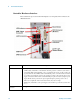
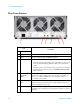
LAN Connectors Gigabit Ethernet (GbE) LAN: two RJ-45 connectors with speed/link/active LED on the faceplate.
Connectors include embedded LEDs:
USB Ports The controller provides four USB 2.0 Type A ports on the faceplate. All USB ports are compatible with
high-speed, full-speed and low-speed USB devices. The controller supports multiple boot devices. The
boot priority and boot device can be configured in BIOS. USB to VGA display adapters are supported.
GPIB Connector The GPIB connector on controller is a micro D-sub 25P connector. It is not used to control the E6630A;
and is not needed in normal operation of the test set. However, it can be used to control external
bench-top instruments. You need the supplied GPIB adapter cable to connect instruments. The
on-board GPIB controller is compatible with the IEEE 488 standard.
Reset Button If it becomes necessary to perform a hard reset of the controller, you can use any pin-shaped object
(such as an unfolded paper clip) to press the front panel reset button.
DVI-I Connector The DVI-I connector connects the controller to a video monitor. DVI-I supports both digital (DVI) and
analog (VGA) monitors. While connecting to an analog (VGA) monitor, you need to install the
DVI-to-VGA adapter, which is shipped with the M9036A controller, on the DVI-I connector. DVI-I
contains both the digital and analog connections, (DVI-D and DVI-A), it's essentially a combination of
DVI-D and DVI-A video output within one connector (and cable). The DVI-I output provides up to
1920x 1200 60 Hz resolution or up to 2048 x 1536 at 75Hz resolution.
Express Card The Express Card 34 slot is not used in operation of the E6630A test set; however, it is available for use
as an I/O expansion accessory.
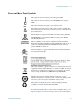
Lever Lock Release
Button
Press the red button down before moving the black ejector/injector handle.
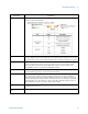
Item Name Description