
Technical data


32 Getting Started Guide
2 Front Panel Features
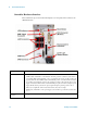
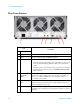
Controller Hardware Interface
The controller is exposed even when the impact cover is in place. The connectors are
illustrated below:
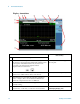
Item Name Description
LED Indicators • SSD (yellow): flashes when Solid State Drive (SSD) is active.
• STATUS (blue): if the LED is on and then turns off during system boot, then the system status is
normal. If the LED continues blinking or stays on, it indicates the system is not able to shut down
properly. When the chassis Inhibit switch is in the Manual position, a controller shutdown results in
an operating system shutdown; however, the controller is not able to shut down the chassis power
supply. As a result, the LED remains on until the Inhibit pin is pulsed low (thus cycling the power
supply) OR the chassis power button is pressed again causing the operating system to reboot.
• WD (red): not significant on this model, but bus activity may cause it to light.
• PWR (green): if the LED is on, the power supply to the controller is good and the system should
boot.
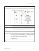
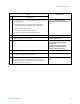
SMB Trigger
Connector
This trigger line is not used by the E6630A.