
Technical data


30 Getting Started Guide
2 Front Panel Features
Input/Output Hardware Interface
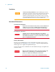
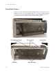
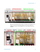
The connectors which are exposed when the impact cover is in place are illustrated
below:
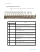
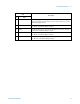
Item
Description
# Name
1 REF IN This BNC input port accepts a timebase reference input. Under the impact cover, it
is routed to the Ref In port of the M9300A Reference module.
2 TRIG 1 This BNC trigger port (for the left sub-instrument) is used for output triggers from
the analyzer. Under the impact cover, it is routed to the Trig 2 port of the M9214A
IF Digitizer module.
3 TRIG 2 This BNC trigger port (for the left sub-instrument) is used for input or output
triggers to or from the source. Under the impact cover, it is routed to the Trig 2 port
of the M9311A Modulator module.
4 TRIG 3 This BNC trigger port (for the left sub-instrument) is an RF blanking trigger which
is supplied to the TRIG 3 port on the E6618A Multiport Adapter. Under the impact
cover, it is routed to the Trig 2 port of the M9310A Source Output module.
5 TRIG IN This BNC trigger port (for the left sub-instrument) accepts an external trigger input
to the analyzer. Under the impact cover, it is routed to the Trig 1 port of the
M9214A IF Digitizer module.
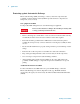
6 TRIG 1 This BNC trigger port (for the right sub-instrument) is used for output triggers from
the analyzer. Under the impact cover, it is routed to the Trig 2 port of the M9214A
IF Digitizer module.
7 TRIG 2 This BNC trigger port (for the right sub-instrument) is used for input or output
triggers to or from the source. Under the impact cover, it is routed to the Trig 2 port
of the M9311A Modulator module.
8 TRIG 3 This BNC trigger port (for the right sub-instrument) is an RF blanking trigger
which is supplied to the TRIG 3 port on the E6618A Multiport Adapter. Under the
impact cover, it is routed to the Trig 2 port of the M9310A Source Output module.