
Technical data


18 Getting Started Guide
1 Quick-Start
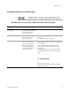
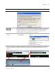
8 Verify the installation a From the mouse right-click
menu, select
Utility, Virtual
Front Panel
. (All
key-presses that follow
refer to the keys shown on
the Virtual Front Panel.)
b Press
System, Show,
System.
c Verify that the purchased
application(s) appear in the
list.
• If you require further assistance, contact the Agilent
support team.
Online assistance: http://www.agilent.com/find/assist
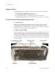
9 Attach a loopback cable a Use an RF cable to connect
the front panel RF In and
RF Out ports for this
sub-instrument.
• The purpose is to use a loopback cable to verify that
the test set’s source can generate a signal and the test
set’s analyzer can measure it.
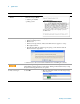
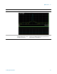
10 Generate and view a
signal
a Press
Input/Output, More,
RF Output & Test Set
Config
, RF Output,
RF Output
.
b Press
AMPTD Y Scale, Ref
Value
, 10, dBm.
c Press
FREQ, Center Freq,
2.4, GHz.
d Press
SPAN X Scale,
Span, 8, MHz.
e Press
Source, Frequency,
2.4, GHz.
f Press
Source, RF Output,
On.
g Press
Source, Amplitude,
RF Power, 0, dBm.
• Select RF Output rather than GPS Output.
• Set the amplitude reference to 10 dBm
• Set the analyzer center frequency to 2.4 GHz.
• Set the analyzer span to 8 MHz.
• Set the source frequency to 2.4 GHz.
• Set the source RF output to On.
• Set the source amplitude to 0 dBm.
• To ensure accurate power levels from the source, see
“Source Level Accuracy" on page 20.
Steps Actions Notes