Agilent E6630A Wireless Connectivity Test Set Notice: This document contains references to Agilent. Please note that Agilent’s Test and Measurement business has become Keysight Technologies. For more information, go to www.keysight.com.
Notices © Agilent Technologies, Inc. 2013-2014 Manual Part Number No part of this manual may be reproduced in any form or by any means (including electronic storage and retrieval or translation into a foreign language) without prior agreement and written consent from Agilent Technologies, Inc. as governed by United States and international copyright laws. E6630-90001 Trademark Acknowledgements Bluetooth ® is a trademark owned by Bluetooth SIG, Inc., U.S.A, and licensed to Agilent Technlogies.
In This Guide… This guide contains the following information: 1 Quick-Start This chapter explains how to initialize the test set and generate and view a signal. 2 Front and Rear Panel Features Refer to this chapter for information on front- and rear-panel key functionality, and display annotations. 3 Test Set Operating System This chapter describes the Microsoft Windows configuration and the settings used with the Agilent test set software.
Contents 1 Quick-Start About the Test Set 10 Instrument Selection 12 Initial Inspection 13 Table.
Display Annotations Rear-Panel Features 36 38 Front and Rear Panel Symbols 39 3 Test Set Operating System Agilent Software Installed 42 Agilent V9060A & V9077A software 42 Customer Installation of Software 43 3rd party software verified by Agilent Installation of other 3rd party software 43 43 User Accounts 44 Administrator login 44 User login 44 AgilentOnly user account 44 Agilent service user accounts 44 Customer creation of accounts 45 Agilent Licensing Options Fixed Perpetual 46 Transportable Pe
Disk defragmenting USB Connections 62 63 Hard Drive Partitioning and Use 64 Hard Drive Recovery Process 65 Updating the software 67 Configuring recovery prompt timing 73 4 Using Microsoft Windows Operating System Navigating Windows Without a Mouse 76 Remote Desktop: Using the Sest Set Remotely 77 Overview of Remote Desktop operation 77 Setting up Remote Desktop operation 77 How to locate the computer name of the test set 79 Running a Remote Desktop session 81 The Virtual Front Panel 90 Capturing/Pr
8 Getting Started Guide
Agilent E6630A Wireless Connectivity Test Set Getting Started Guide 1 Quick-Start This section explains how to initialize the test set and generate and view a signal.
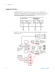
1 Quick-Start About the Test Set The E6630A Wireless Connectivity Test Set contains one or two transmit/receive instruments containing an RF source and an RF analyzer. Each instrument is run by its own instance of the XSA firmware application (a fully loaded test set shows two independent XSA windows on its monitor display). The test set is typically used in conjunction with the E6618A Multiport Adapter, as illustrated below.
Quick-Start 1 The multiport adapter splits the downlink RF signal from the test set’s source into eight RF output paths. All eight output paths can be active at once, or the user can activate a subset of them in any desired combination. Each path interfaces to an RFIO port through a coupler, so that the RFIO port can also return an uplink signal to the analyzer in the test set.
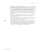
1 Quick-Start Instrument Selection On the monitor or remote desktop view of the test set, each of the two instruments is represented by a separate XSA window. You can identify which TRX a window controls by looking for the identifier (“Left” or “Right”) at the top left corner of the window. Although the test set as a whole is assigned only one IP address for the entire PXIe chassis, the individual instruments within the chassis can be differentiated in network communication with the test set.
Quick-Start 1 Initial Inspection Inspect the shipping container and the cushioning material for signs of stress. Retain the shipping materials for future use, as you may wish to ship the test set to another location or to Agilent Technologies for service. Verifying the contents Item Deliverable Description Getting Started Guide Provides first-time power on instructions, licensing information, operating system information, and general hardware information.
1 Quick-Start Shipping problems? If the shipping materials are damaged or the contents of the container are incomplete: • • • Contact the nearest Agilent Technologies office. Keep the shipping materials for the carrier’s inspection. If you must return an test set to Agilent Technologies, use the original (or comparable) shipping materials. See “Returning a test set for Service" on page 101.
Quick-Start 1 Turning on the test set the first time During the initial power-on process, the test set turns off and restarts several times. This only happens during the initial installation process. Initializing the test set using a USB mouse and external monitor Steps Actions 1 Connect a mouse and keyboard • Connect the mouse and 2 Connect a VGA monitor • Connect the monitor to the keyboard to two of the USB ports on the front panel panel of the test set.
1 Quick-Start Steps Actions 4 Launch Microsoft Setup Wizard • Highlight Microsoft Notes Windows and press Enter to start the pre-installed operating system. a The analyzer performs the following steps: • Windows Startup window • Black screen • Windows message window, “Please wait while windows prepares to setup” • Blue Agilent window • The following Welcome window appears giving you information about the End-User License Agreement.
Quick-Start Steps Actions 1 Notes • This window appears and covers the LaunchXSA window. If you do not check the “Do not show this message again” check box, this message will be displayed each time the analyzer is turned on. No application will start while this message is displayed. Before continuing, make sure that you carefully read the Anti-Virus message and determine what action is appropriate. 6 Disable the Anti-Virus message a Select the check box and click Continue.
1 Quick-Start Steps Actions 8 Verify the installation a From the mouse right-click • If you require further assistance, contact the Agilent support team. menu, select Utility, Virtual Online assistance: http://www.agilent.com/find/assist Front Panel. (All key-presses that follow refer to the keys shown on the Virtual Front Panel.) b Press System, Show, System. c Verify that the purchased application(s) appear in the list.
Quick-Start Steps Actions 1 Notes The 2.4 GHz signal appears on the display. 11 Getting Started Guide If an E6618A Multiport Adapter will be used, connect the E6618A hardware. Procedures for connecting the E6618A Multiport Adapter to the E6630A Test Set are presented in the Started Guide for the E6618A.
1 Quick-Start Source Level Accuracy To ensure accurate power levels from the Vector Signal Generator, two adjustments need to be run; they are known as Source Alignment and Power Search. Source Alignment This alignment is needed when you change the source output frequency, and also when the instrument’s internal temperature has drifted more than 4 degrees C since the alignment was last performed (temperature can be checked by sending a SCPI command (:CAL:TEMP:CURR?).
Quick-Start 1 Options The options installed on the test set are listed on the System > Show > System display. Anti-Virus Software and Firewalls No anti-virus software is shipped with the test set. It is recommended that you install anti-virus software if your test set is connected to the LAN. Check with your IT department to see what they recommend. The test set is shipped with the Windows firewall enabled.
1 Quick-Start Instrument Information Power requirements The only physical installation of your Agilent test set is a connection to a power source. Line voltage does not need to be selected. This test set does not contain customer serviceable fuses. This is a Safety Class 1 Product (provided with a protective earthing ground incorporated in the power cord). The mains plug shall only be inserted in a socket outlet provided with a protective earth contact.
1 Quick-Start AC power cord The test set is equipped with a three-wire power cord, in accordance with international safety standards. This cable grounds the test set cabinet when connected to an appropriate power line outlet. The cable appropriate to the original shipping location is included with the test set. See: http://www.agilent.com/find/powercords Always use the three-prong AC power cord supplied with this product.
1 Quick-Start Ventilation VENTILATION REQUIREMENTS: When installing the product in a cabinet, the convection into and out of the product must not be restricted. The ambient temperature (outside the cabinet) must be less than the maximum operating temperature of the product by 4oC for every 100 watts dissipated in the cabinet. If the total power dissipated in the cabinet is greater than 800 watts, then forced convection must be used.
Quick-Start Getting Started Guide 1 25
1 Quick-Start Protecting against electrostatic discharge Electrostatic discharge (ESD) can damage or destroy electronic components (the possibility of unseen damage caused by ESD is present whenever components are transported, stored, or used). Test equipment and ESD To help reduce ESD damage that can occur while using test equipment: Do not use these first three techniques when working on circuitry with a voltage potential greater than 500 volts.
Agilent E6630A Wireless Connectivity Test Set Getting Started Guide 2 Front Panel Features This section describes the following features: “Front-Panel Features" on page 28 “Display Annotations" on page 36 “Rear-Panel Features" on page 38 “Front and Rear Panel Symbols" on page 39 Agilent Technologies 27
2 Front Panel Features Front-Panel Features The test set consists of instruments loaded in a PXI rack. There is a controller (located on the far left) and one or two sub-instruments, which are protected by a translucent impact cover and are not exposed during normal operation. A hardware interface at the top of the rack provides access to inputs and outputs for RF and trigger signals.
2 Front Panel Features Each of the sub-instruments under the impact cover includes a Vector Signal Generator (M9381A) and a Vector Signal Analyzer (M9391A). If both sub-instruments are installed, they share the Controller (M9036A) and a common Frequency Reference (M9300A).
2 Front Panel Features Input/Output Hardware Interface The connectors which are exposed when the impact cover is in place are illustrated below: Item Description # 30 Name 1 REF IN This BNC input port accepts a timebase reference input. Under the impact cover, it is routed to the Ref In port of the M9300A Reference module. 2 TRIG 1 This BNC trigger port (for the left sub-instrument) is used for output triggers from the analyzer.
2 Front Panel Features Item Description # Name 9 TRIG IN This BNC trigger port (for the right sub-instrument) accepts an external trigger input to the analyzer. Under the impact cover, it is routed to the Trig 1 port of the M9214A IF Digitizer module. 10 RF OUT This Type N RF output port (for the left sub-instrument) is connected to the DUT or to RF IN on the E6618A Multiport Adapter.
2 Front Panel Features Controller Hardware Interface The controller is exposed even when the impact cover is in place. The connectors are illustrated below: Item Name LED Indicators SMB Trigger Connector 32 Description • SSD (yellow): flashes when Solid State Drive (SSD) is active. • STATUS (blue): if the LED is on and then turns off during system boot, then the system status is normal. If the LED continues blinking or stays on, it indicates the system is not able to shut down properly.
2 Front Panel Features Item Name Description LAN Connectors Gigabit Ethernet (GbE) LAN: two RJ-45 connectors with speed/link/active LED on the faceplate. Connectors include embedded LEDs: USB Ports The controller provides four USB 2.0 Type A ports on the faceplate. All USB ports are compatible with high-speed, full-speed and low-speed USB devices. The controller supports multiple boot devices. The boot priority and boot device can be configured in BIOS. USB to VGA display adapters are supported.
2 Front Panel Features Virtual Front Panel The E6630A model does not include physical front-panel keys. However, if you have a PC mouse, monitor, and keyboard plugged in (or are working through a Remote Desktop interface), you can navigate front-panel functions using the virtual front panel (VFP) shown below. Access the VFP as follows: 1. Right-click the mouse. 2. Left-click Utility (1) in the menu, as shown below. 3. Left-click Virtual Front Panel (2) in the menu, as shown below.
2 Front Panel Features On the VFP the keys labeled "Key 1" through "Key 7" function as the menu keys. Using the mouse to click on a combination of the VFP keys and the menu keys on the display screen, you can operate the instrument as if it had conventional front-panel keys. The VFP frame shows “Left” or “Right” at the upper left corner of the frame, so that it’s clear which sub-instrument within the PXI rack is being controlled by it.
2 Front Panel Features Display Annotations Item # 36 Function Key Description 1 Measurement bar; shows general measurement settings and information. Some measurements include limits which the data is tested against. A Pass/Fail indication may be shown in the lower-left corner. The following graphics indicate single/continuous measurement: All the keys in the test set Setup part of the front panel.
2 Front Panel Features Item # 6 Function Key Description Settings panel; displays system information that is not specific to any one application. • Input/Output status - green LXI indicates the LAN is connected.
2 Front Panel Features Rear-Panel Features Item # 38 Description Name 1 Line power input The AC power connection. See the product specifications for more details. 2 FAN Fan speed control (settings are HIGH and AUTO). 3 INHIBIT Inhibit switch. The settings are DEF (default) and MAN (manual). • When the switch is in the default position, the chassis is powered up by the front panel ON/Standby pushbutton. This is the recommended setting.
2 Front Panel Features Front and Rear Panel Symbols This symbol is used to indicate power ON (green LED). This symbol is used to indicate power STANDBY mode (yellow LED). This symbol indicates the input power required is AC. The instruction documentation symbol. The product is marked with this symbol when it is necessary for the user to refer to instructions in the documentation. The CE mark is a registered trademark of the European Community.
2 40 Front Panel Features Getting Started Guide
Agilent E6630A Wireless Connectivity Test Set Getting Started Guide 3 Test Set Operating System This chapter describes the Microsoft Windows configuration and the settings used with the Agilent test set software. It includes information about changing some of the system settings. And it describes the Windows operating system configuration and the software installations that are present on the hard disk drive when the test set leaves the factory.
3 Test Set Operating System Agilent Software Installed Agilent V9060A & V9077A software The Agilent V9060A IQ Analyzer application and the Agilent V9077A WLAN measurement applications (802.11a/b/g, 802.11n, and 802.11ac) are installed by default in the test set, but these must be licensed in order to be used. Whichever licenses were purchased with the instrument are installed at the factory (for example, V9077A-2FP, V9077A-3FP, V9077A-4FP).
Test Set Operating System 3 Customer Installation of Software 3rd party software verified by Agilent Agilent has verified that the following programs are compatible with the test set applications: • Symantec AntiVirus™ Corporate Edition version 10 • MathWorks MATLAB Installation of other 3rd party software The E6630A platform is an open Windows environment, so you can install non-approved software on the test set. However, installation of non-approved software may affect test set performance.
3 Test Set Operating System User Accounts Administrator login The Administrator account ships from the factory with the password “agilent4u”.
Test Set Operating System 3 Customer creation of accounts You can create additional user accounts and decide on the level of security granted to any new user accounts created. For example, the level of security can be assigned as administrator, power user, user, backup operators. User names are not case sensitive but passwords are case sensitive. For the test set software to operate, the user account executing the software must be assigned Administrator or Power User privileges.
3 Test Set Operating System Agilent Licensing Options Agilent test sets use three licensing types: Fixed Perpetual, Transportable Perpetual, and Trial. Fixed Perpetual licenses are also required to enable hardware options. Fixed Perpetual Fixed Perpetual licenses are the traditional license type (Fixed) with the same duration (Perpetual) that have been available for all features since the Agilent X-Series introductions.
Test Set Operating System 3 Time-Limited Licenses Trial licenses Trial licenses are available so that you may try applications before you buy the full applications. These licenses are time limited for a 14 day period, and are restricted to one trial for an individual application per instrument. The restriction is enforced through the license redemption process of the Agilent Software Manager (ASM) system.
3 Test Set Operating System Licensing New Measurement Application Software - After Initial Purchase Additional measurement application software can be ordered after your initial purchase of the E6630A test set. Software upgrades are provided in a kit that includes an option based Entitlement Certificate, a license agreement. The licenses are downloaded from the license Web site onto a storage device so they can be loaded into the instrument.
3 Test Set Operating System Step Action Notes 4 Verify installation a Cycle the power on the signal test set. b On the Virtual Front Panel press System, Show, System. c Verify that the new application appears in the list. The application will not be available for use until after the power has been cycled This displays the list of installed applications. If you require further assistance, please contact the Agilent support team. Online assistance: http://www.agilent.
3 Test Set Operating System Transporting a License Between Test Sets Transportable licenses can be identified by the letters "TP" in their option designator. For example, V9077A-2TP indicates the license is transportable and perpetual. To transport this license from one test set to another, Agilent recommends that both test sets be at the same instrument software release. This ensures that the user experience is identical between instruments.
3 Test Set Operating System Step Action 4 Start the License Manager on the Source Instrument • On the source instrument, press System, 5 Transport the Transportable License from Source Instrument a On the source instrument, locate the desired license to be transported and highlight it. Its option designator should include the letters "TP". b .Right-click on the mouse and select Delete. c Click Yes in the License Deletion Confirmation dialog box.
3 Test Set Operating System Step Action Notes 8 Install License File in Target Instrument a With the target instrument running, insert the USB flash drive into one of the front panel USB ports. After a few minutes, you should see a message saying "Successful License Installation" The Agilent License Services running on the target instrument looks for *.lic files whenever it detects a USB device has been inserted. If the contents of the *.
Test Set Operating System 3 Windows Configuration The Windows settings have been optimized for the best measurement performance. Any modifications to these settings may degrade test set performance and measurement speed. In general, most Windows System settings (typically set through the Windows Control Panel) should not be modified. Those that can be safely modified are listed below.
3 Test Set Operating System You may use this feature To do this... Install and configure a printer. Set the time and date. Modify System Properties, Advanced Tab settings of Performance, Adjust for Best Performance. Leave all other settings unchanged. Settings that must not be changed Avoid changing any settings in this section. Changes to the following settings may degrade test set performance, screen displays, and measurement speed. Do NOT use this To do this...
Test Set Operating System 3 Do NOT use this To do this... feature Do not delete or modify the “AgilentOnly” user account. In addition, DO NOT: • Add, delete, or modify hard-disk drive partitions. • Delete or modify Agilent registry entries.
3 Test Set Operating System Configuring Printers Printers are configured using the Microsoft Windows Control Panel. It is easily accessed from the Windows Start menu or from under the front panel System key. This setup process is most easily done using a USB mouse and an external keyboard. When setting up a new printer, you may need to load the printer driver (unless you are using a network printer that your IT department has set up to include the driver).
Test Set Operating System 3 Configuring LAN Hostname The Computer Name, or hostname, is pre-configured from the factory. It must be a unique name so that it does not conflict with other equipment on your LAN. The pre-configured Computer Name is A-E6630A-xxxxx, where xxxxx represents the last 5 digits of the test set serial number. To change the Computer Name consult the Microsoft Windows Help and Support Center. IP Address & Gateway The test set is pre-configured to obtain an IP Address using DHCP.
3 Test Set Operating System Windows Security Microsoft recommends the following to ensure the test set Windows operating system is protected: • Use an internet firewall. • Get the latest critical Windows updates. • Use up-to-date antivirus software. To check the status or make changes in the security settings for your test set, open the Windows Security Center, click Start, Control Panel, and then click Security Center. The window may look slightly different on your test set.
Test Set Operating System 3 Windows Firewall The test set is shipped with the Windows Firewall enabled. The window may look slightly different on your test set. Windows Firewall Exceptions for programs and ports have been added to allow proper operation of the test set over a network. Modifying these settings may cause the test set to not operate properly.
3 Test Set Operating System Be aware that downloading and installing Windows Updates can be network and CPU usage intensive (impacting the test set performance), and some Windows Updates automatically reboot the test set. It is recommended that Windows Updates be performed when the test set is not in normal use. Virus protection There is no antivirus software included with your test set. Antivirus application software has been tested to be compatible with the test set.
Test Set Operating System 3 Spyware protection There is no anti-spyware software installed on the test set. This should not be a problem if you do not use the test set for a lot of internet browsing. Having spyware in the test set could have an impact on the test set performance.
3 Test Set Operating System System Maintenance Backup It is recommended that you have a regular backup strategy. Your IT department may already have a backup strategy in place which is suitable for the test set and its data. Using the Agilent Recovery system in conjunction with a regular backup strategy should allow full recovery of the test set data. The Windows operating system has a Backup utility that you can use to archive files and folders in case of a hard disk drive failure.
Test Set Operating System 3 USB Connections All of the USB ports are compatible with the USB 2.0 and 1.1 specification. The four USB ports on the front panel of the M9036A Controller (see graphic below) are USB Series “A” ports. These are ports to which you can connect USB mass storage devices, accessories such as printers and keyboards, and the E6618A Multiport Adapter.
3 Test Set Operating System Hard Drive Partitioning and Use The drive is partitioned into 3 sections: C:, D: and E: 64 • The C: partition contains the Windows operating system and software installed by Agilent. This is an Open System which means you can install additional software, and these should be installed on the C: drive. However, only a limited set of software applications are tested for use with the Agilent measurement software.
3 Test Set Operating System Hard Drive Recovery Process The Agilent Recovery System can be used to repair errors on the test set's C: drive partition, or to restore the original factory configuration of the system software. The Agilent Recovery System is stored in a separate hidden hard disk drive partition. Repairing errors on the hard disk drive may result in loss of data or files.
3 Test Set Operating System Using the test set recovery system Step Notes 1 Make sure the test set is turned off. 2 Turn on the test set. • Press the down arrow key to move the highlight to Agilent Recovery System, then press Enter. After the Agilent Technologies screen is displayed, this screen is displayed for five seconds. 3 When the Agilent Recovery System has booted, follow the on-screen instructions to recover the image of the C: drive. • Press 2, then press Enter to select the recovery.
3 Test Set Operating System Updating the software The purpose of this update is to ensure that the E6630A’s software, its measurement mode applications, and the FPGA content of its PC boards are all current and up to date. NOTE An update to the instrument software revision does not require a new license key for the measurement applications, so long as the applications were licensed prior to the update.
3 Test Set Operating System User account and log-in The default user account is Instrument, which does not have the required permissions to install the instrument software updates. For the process outlined below, the user must be logged in as Administrator. The automated instrument software upgrade process has an install wizard which removes the old software version and installs new software version without manual steps.
Test Set Operating System 3 Preparing the installation Step Notes 2 A window appears showing the extraction of the software installer. Click Install in the confirmation window to begin the installation process. When the extraction process is complete, a software updater display appears, showing progress of the software removal and installation. The update process causes various messages and windows to appear and disappear on the screen, but the process doesn’t require further interaction.
3 Test Set Operating System Preparing the installation Step Notes Software updater window, showing uninstallation progress: While the old instrument software is being uninstalled, the text “Uninstall in Progress” text rolls across the screen, to be replaced finally by “Completed Successfully”. No interaction is required at this point.
Test Set Operating System 3 Preparing the installation Step Notes FPGA update warning window (may be displayed, if any FPGA updating occurs): CAUTION During FPGA programming, DO NOT power off the E6630A for ANY reason! Interrupting the FPGA update process can place the instrument in an unusable state, requiring it to be returned to Agilent for repair. 3 When the software updater window shows “The software upgrade was successful”, you will be prompted to reboot.
3 Test Set Operating System Preparing the installation Step Notes 4 After the E6630A restarts, it will boot up in the default “Instrument” account, perform alignments, and finally display the measurement screen. If the instrument does not reboot, remove the USB storage device and cycle power. The boot order for the instrument may have been changed in the instrument BIOS previously, and the instrument may be instructed to boot from USB first, and the internal drive second.
Test Set Operating System 3 Configuring recovery prompt timing You can configure the time at which the test set power-up process waits for the selection of the recovery process by performing the following steps: Step Notes 1 Right-click My Computer, and click Properties. This accesses the System Properties tabbed page. 2 Click the Advanced tab. 3 In the Startup and Recovery section, click Settings.
3 74 Test Set Operating System Getting Started Guide
Agilent E6630A Wireless Connectivity Test Set Getting Started Guide 4 Using Microsoft Windows Operating System The capabilities described in this section are Microsoft Windows features. The following information provides some guidelines for using the capabilities with the test set. You need to refer to the Windows help documentation for more information. Your version of Windows may not match these instructions exactly. You need an external keyboard and mouse to fully use these features.
4 Using Microsoft Windows Operating System Navigating Windows Without a Mouse Key Presses Actions Esc Exits/closes a Windows dialog box (does not exit an Application window) Enter Does the current "default action". If a menu item or a button is currently highlighted, then the Enter key activates that menu item or button.
4 Using Microsoft Windows Operating System Remote Desktop: Using the Sest Set Remotely Windows Remote Desktop is recommended for remote control of the test set. The Remote Desktop functionality is a Microsoft Windows capability. The following discussion provides some guidelines for using this capability with the test set. You need to refer to the Windows help documentation for more information. As Windows evolves, these instructions may no longer be exact.
4 Using Microsoft Windows Operating System Setting up a remote desktop connection Step Notes 2 On the test set, open the Windows Control Panel. • Using the Virtual Front Panel within the test set application, press System, Control Panel, or, From the Windows Desktop, click Start, Control Panel. 3 Within the Control Panel, select System, System and Security. 4 Click Remote Settings. A System Properties window appears, with the Remote tab displayed.
4 Using Microsoft Windows Operating System Remote computer running another version of Windows You can use any 32-bit version of Windows (Windows 95, 98, ME, NT4, or 2000) to install and run the Client software for Remote Desktop Connectivity. However, you need to have available a Windows XP or Windows 7 installation CD-ROM, because that contains the Client software. The following instructions relate to software provided by Microsoft Corporation.
4 Using Microsoft Windows Operating System Locating the name from the Windows desktop (with a mouse): Step 2 The computer name is displayed in the System window, under the heading “Computer name, domain, and workgroup settings”. Notes The Computer Name is listed as Full computer name. Locating the name from the Windows desktop (without a mouse): Step Notes 1 Press Ctrl+Esc to display the Windows Start menu. 2 Use the Up Arrow or Down Arrow keys to select the Control Panel item.
Using Microsoft Windows Operating System 4 Running a Remote Desktop session Initializing a Remote Desktop session To initialize a Remote Desktop Session, you need to know the Computer Name of the test set. This information can be shown on the test set display by following the procedure in the section “How to locate the computer name of the test set" on page 79.
4 Using Microsoft Windows Operating System • “Accessing menus for Remote Desktop operation" on page 85 • “Keycode commands for Remote Desktop operation" on page 86 • “The Virtual Front Panel" on page 90 Setting Remote Desktop options Step Notes 1 On the Remote Desktop Connection menu, click Options. The Options dialog has several tabs. Generally, the default settings are correct. 2 Under the General tab, ensure that the Computer name, User name and Domain name are set correctly.
Using Microsoft Windows Operating System Step 4 Notes 3 Click the Display tab. • Under Remote desktop size, you may select the size of the window in which the test set display appears. Do not select any size smaller than 1024 x 768 pixels. Selecting a remote desktop size smaller than 1024 x 768 results in the test set display not being fully visible. In such circumstances, scroll bars do not appear, so portions of the display are not accessible.
4 84 Using Microsoft Windows Operating System Step Notes 5 Click the Experience tab. To Optimize the performance of the Remote Desktop session, choose the appropriate connection format from the drop-down list.
Using Microsoft Windows Operating System 4 Accessing menus for Remote Desktop operation Using the mouse, right-click the application display window to access the following remote desktop menus: The function of each selection in the menu is generally identical to that of the corresponding Virtual Front Panel key. The following lists additional functionality: Exit – Selecting this item closes the Application software. Utility > Page Setup – Selecting this item opens a printer setup dialog.
4 Using Microsoft Windows Operating System Keycode commands for Remote Desktop operation When using the test set in remote desktop mode, the following combinations of remote keyboard keys can be used to perform the operation of the virtual front-panel keys.
4 Using Microsoft Windows Operating System Keycode commands Getting Started Guide To initiate the following virtual key: Press these keys on the remote computer keyboard: Cont Ctrl+Alt+C Ctrl Ctrl Decrease Audio Volume the Volume Control slider Del Delete Down Arrow Down Arrow Enter Enter (Return) File Ctrl+F FREQ Channel Ctrl+Shift+F Full Screen Ctrl+Shift+B Help F1 Increase Audio Volume the Volume Control slider Input/Output Ctrl+Shift+O Left Arrow Left Arrow Marker Ctrl+A
4 Using Microsoft Windows Operating System Keycode commands 88 To initiate the following virtual key: Press these keys on the remote computer keyboard: Right Arrow Right Arrow Save Ctrl+S Select Space Bar Single Ctrl+Alt+S Softkey 1 Ctrl+Shift+F1 Softkey 2 Ctrl+Shift+F2 Softkey 3 Ctrl+Shift+F3 Softkey 4 Ctrl+Shift+F4 Softkey 5 Ctrl+Shift+F5 Softkey 6 Ctrl+Shift+F6 Softkey 7 Ctrl+Shift+F7 Source Ctrl+Alt+U SPAN X Scale Ctrl+Shift+S Split Screen Ctrl+Shift+L Sweep/Control Ct
Using Microsoft Windows Operating System 4 Keycode commands To initiate the following virtual key: Press these keys on the remote computer keyboard: 7 7a 8 8a 9 9a – Use the – key to enter a negative value, as appropriatea . (Decimal Point) . (Period)a 0 (Zero) 0 (Zero)a a. For remote keyboards that feature a numeric keypad, use either the appropriate numeric keypad key or the main keypad key.
4 Using Microsoft Windows Operating System The Virtual Front Panel The Virtual Front Panel is a software equivalent of the front-panel key set, which provides another alternate method for test set control. It may be displayed in a separate window on the test set (or remote desktop) display. The Virtual Front Panel is also available when using the test set directly, provided that a mouse or other pointing device is attached to it.
Using Microsoft Windows Operating System 4 Capturing/Printing Displays and Windows You need an external keyboard and mouse to use this feature. Save the desktop: Step Notes 1 Press Print Screen on the external keyboard This captures the desktop and saves it on the Windows clipboard. 2 Open a graphics software program like Microsoft Paint 3 Paste the clipboard contents into the program The keyboard shortcut Ctrl + v will paste the contents of the clipboard.
4 Using Microsoft Windows Operating System Windows Shortcuts and Miscellaneous Tasks This section provides a list of Windows shortcuts (key combinations) that are useful when you operate the test set without an attached mouse and keyboard. (See also “Navigating Windows Without a Mouse" on page 76.) Although these shortcuts are available in any Windows system, they are not commonly used when a mouse and keyboard are attached.
4 Using Microsoft Windows Operating System Navigating an Application Menu without a Mouse or Keyboard This example uses Microsoft Excel, but you can use a similar sequence of operations to select and execute any menu item of any application. To select and execute the item Sheet > Rename option from the Format menu in the menu bar shown below, perform the following operations: Step Notes 1 Press Alt to select the File menu in the menu bar. The focus must be in the appropriate window.
4 Using Microsoft Windows Operating System If a mouse is attached to the test set, and you move the mouse cursor to the bottom of the display (either deliberately or accidentally), the taskbar automatically appears. Provided that the taskbar is in auto-hide mode, you can make it disappear again by moving the mouse cursor away from the bottom of the screen.
Using Microsoft Windows Operating System 4 Restoring taskbar auto-hide mode Step Notes 5 Click OK. This applies the change and closes the dialog box. Windows startup folder All Windows systems include a special folder, called the Startup folder. If a program, or a shortcut to a program, is placed in the Startup folder (either by Windows itself, or by a third-party application, or by any user), that program automatically runs every time Windows is restarted.
4 96 Using Microsoft Windows Operating System Getting Started Guide
Agilent E6630A Wireless Connectivity Test Set Getting Started Guide 5 Troubleshooting “Check the Basics" on page 98 “Problems with Microsoft Windows Operating System" on page 100 “Returning a test set for Service" on page 101 No operator serviceable parts inside. Refer servicing to qualified personnel. To prevent electrical shock do not remove covers.
5 Troubleshooting Check the Basics o Is there power at the receptacle? o Is the test set turned on? Check to see if the green LED beside the power switch is on. Also, listen for internal fan noise to determine if the test set cooling fans are running. o If other equipment, cables, and connectors are being used with your test set, make sure they are connected properly and operating correctly.
Troubleshooting 5 o If the previously performed alignments did not resolve the problem, press System, Alignments, Restore Align Defaults. Then press System, Alignments, Align Now, All. o Is the test set displaying an error message? If so, refer to the Instrument Messages Guide. o Check if the external frequency reference is selected but not available. Verify that it is selected by pressing Input/Output, Freq Ref In.
5 Troubleshooting Problems with Microsoft Windows Operating System The Microsoft Windows operating system settings have been optimized for the best performance. Modification of these settings may degrade test set performance and measurement speed. Those that can be safely modified are described in “Settings that can be changed" on page 53. The E6630A Wireless Connectivity Test Set operates in an open Windows environment, so you can install software on the test set.
5 Troubleshooting Returning a test set for Service Calling Agilent Technologies Agilent Technologies has offices around the world to provide you with complete support for your test set. To obtain servicing information or to order replacement parts, contact the nearest Agilent Technologies office listed in the following table. In any correspondence or telephone conversations, refer to your test set by its product number, full serial number, and software revision.
5 Troubleshooting Russia +7 (495) 797 3930 Spain 91 631 3300 Sweden 0200-88 22 55 United Kingdom +44 0 118 927 6201 Online assistance: http://www.agilent.com/find/assist Contact us: http://www.agilent.com/find/contactus Read the Warranty The warranty for your test set is in the front of your Specifications Guide. Please read it and become familiar with its terms. If your test set is covered by a separate maintenance agreement, please be familiar with its terms.
5 Troubleshooting Packaging the Test Set Use original packaging or comparable. It is best to pack the unit in the original factory packaging materials if they are available. Test set damage can result from using packaging materials other than those specified. Never use styrene pellets in any shape as packaging materials. They do not adequately cushion the test set or prevent it from shifting in the carton.
5 104 Troubleshooting Getting Started Guide
Index Symbols D .
Index M Microsoft SQL Server Desktop Engine, 55 Microsoft Visual J# .
Index Windows 7 operating system, 75 Windows Classic Style, 54 Windows firewall, 59 Windows Remote Desktop, 77 keycodes, 86 options, 82 Options Dialog Experience Tab, 82 General Tab, 82 popup menus, 85 running, 81 Setting up Remote Computer, 78 setting up the E6630A, 77 Setting up Windows Systems, 78 32-bit, 78 virtual front panel, 90 windows security, 58 Windows services, 55 Windows settings, 53 Windows Style, 54 Windows updates, 59 Getting Started Guide 107
Index This information is subject to change without notice. © Keysight Technologies, 2014 Published in USA, December 2014 E6630-90001 www.keysight.