
User`s guide


220 Agilent E6474A User’s Guide
E Permanent In-Vehicle Hardware Installation
Interior Connections
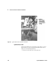
1 Remove approximately 2” (5 cm) of the outer jacket of the
speed pulse cable, where the cable comes through the
firewall (under the dashboard).
2 Cut the red and the white wires at the midpoint of the jacket
opening.
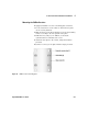
3 Solder the red and white wires of the cable section routed
from the engine compartment to the green wire of the
frequency divider, then cover the connection with shrink
tubing. Figure 77 shows connections to the frequency divider.
4 Solder the red and white wires of the cable section routed to
the navigator to the yellow wire of the frequency divider,
then cover the connection with shrink tubing.
5 Connect the red lead of the frequency divider to an
ignition-switched +12 VDC source, such as the radio fuse. Use
appropriate connectors.
6 Connect the black lead of the frequency divider to chassis
ground. Use appropriate connectors.
7 Secure the frequency divider to a flat surface using Velcro or
an equivalent method.