Agilent TS-5000 Series Automotive Functional Test System E6198B Switch/Load Unit Software Manual Agilent Technologies
Notices © Agilent Technologies, Inc. 2007 Manual Part Number No part of this manual may be reproduced in any form or by any means (including electronic storage and retrieval or translation into a foreign language) without prior agreement and written consent from Agilent Technologies, Inc. as governed by United States and international copyright laws. E6198-90020 Edition First Edition, March 2007 Printed in Malaysia Agilent Technologies Microwave Products (Malaysia) Sdn. Bhd.
Contents 1 Introduction What’s in This Guide? 1- 2 Switch Load Unit Software Overview 2 Installing The Driver How To Install The Driver 3 1- 3 2- 2 Programming With TestExec SL Procedure of Programming TestExec SL Specific Handler 3- 2 Start With System Configuration Editor 3- 2 Configuring an Agilent E6198B Switch/Load Unit 3- 3 Example of a Switch/Load Unit Parameter Block Data Values Example of a Switch/Load Unit Wiring Configuration Values Example Of Using TxSL To Call SLUHandler 3-6 3-4 3-5
THIS PAGE IS INTENTIONALLY LEFT BLANK.
Agilent TS-5000 Series Automotive Functional Test System E6198B Switch/Load Unit Software Manual 1 Introduction The Agilent Switch Load Unit (SLU) E6198B can be installed for use with Agilent TestExec SL or any other commercial/self-developed test execution software. The generic handler can be used with any C/C++ and Visual Basic base software. For those using Agilent TestExec SL, there is the specific handler included with the installation software, SLUHandler.dll.
1 Introduction What’s in This Guide? This chapter provides an overview of new driver. Subsequent chapters in this guide address the following topics: • Chapter 2 — Installing the Driver • Chapter 3 — Programming TxSL specific handler • Chapter 4 — Programming with generic handler provides guidelines for how to communicate E6198B with system specific software. • Glossary includes a glossary of terms and their definitions.
Introduction 1 Switch Load Unit Software Overview Switching is useful in functional testing of complex units under test (UUT). As the complexity rises, so does the UUT pin count resulting in a significant increase for switching. Test execution softwares with the right application tool help us manage switching in a functional test system. The E6198B Switch/Load Unit comes with a generic software handler that can be integrated easily to help us manage the switching.
1 Introduction THIS PAGE IS INTENTIONALLY LEFT BLANK.
Agilent TS-5000 Series Automotive Functional Test System E6198B Switch/Load Unit Software Manual 2 Installing The Driver The CD will include the following: • SLU Handler Dynamic Link Lybrary (DLL) • Agilent E6198B Switch\Load Unit Hardware Manual • Agilent E6198B Switch\Load Unit Software Manual Agilent Technologies 2-1
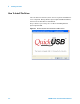
2 Installing The Driver How To Install The Driver Once CD has been inserted, there are two separate installations to be completed. Firstly, Bitwise System Quick USB installation, and next is the SLU Driver installation. Step 1: Please open “setup.exe” at CD for installing Bitwise System Quick USB.
2 Installing The Driver Step 2: Click Next to start InstallShield Wizard Figure 2-2 Bitwise System Quick USB Installation Interface Continue.. Step 3: Accept the term of license agreement and click Next Figure 2-3 Bitwise System Quick USB Installation Interface Continue...
2 Installing The Driver Step 4: Read the following ReadMe Information then click Next Figure 2-4 Bitwise System Quick USB Installation Interface Continue... Step 5: Insert User name and Organization then click Next Figure 2-5 Bitwise System Quick USB Installation Interface Continue...
Installing The Driver 2 Step 6: Choose installation folder path then click Next Figure 2-6 Bitwise System Quick USB Installation Interface Continue... Step 7: Select “Typical” setup type (Recommend) then click Next Figure 2-7 Bitwise System Quick USB Installation Interface Continue...
2 Installing The Driver Step 8: Installation is ready to start, click Install to proceed. Figure 2-8 Bitwise System Quick USB Installation Interface Continue... Step 9: Click Finish to exit Bitwise Quick USB Installation After installing Bitwise Quick USB successfully, the following is to install SLU Handler DLL.
Installing The Driver 2 Step 2: Choose install folder path then click Next Figure 2-10 SLU Plus Installation Interface Continue... Step 3: Install if ready to start installation Figure 2-11 SLU Plus Installation Interface Continue...
2 Installing The Driver Step 4: Click Finish to exit the installation procedure Figure 2-12 SLU Plus Installation Interface Continue...
Agilent TS-5000 Series Automotive Functional Test System E6198B Switch/Load Unit Software Manual 3 Programming With TestExec SL This chapter describes how to program with TestExec SL to call Agilent E6198B Swith/Load Unit, Load Cards and Pin Matrix Module.
3 Programming With TestExec SL Procedure of Programming TestExec SL Specific Handler Start With System Configuration Editor To find out more about the System Configuration Editor, please refer to the section under "Advantage Of Installing Agilent TS-5000 Application Software". System Configuration Editor version 6.0.2 should be installed before use with TestExec SL. The System Configuration Editor (SCE) allows you to configure system hardware and topology layers.
Programming With TestExec SL 3 Configuring an Agilent E6198B Switch/Load Unit Figure 3-14 The parameters that can be configured of an Agilent E6198B Switch/Load Unit. Name of switch /load unit. This is the name referenced in a testplan Click on checkbox, if not checked, to enable switch / load unit to be accessible from testplans Description of switch /load unit. Change if needed. Descriptive keyword to aid in finding the switch /load box in the system.
3 Programming With TestExec SL Example of a Switch/Load Unit Parameter Block Data Values Table 3-1 Typical values in a Parameter Block. Name Value Description Device ID E6198B Instrument Identifier, usually the model number of the Switch/Load Unit. SBIOMode 0 Specifies the I/O method used to communicate the switchBox. E6198B: 8 for USB. Load Box# 0 The number of the Switch/Load Unit. A number “0” indicates the first Switch/Load Unit, and so on.
3 Programming With TestExec SL Example of a Switch/Load Unit Wiring Configuration Values Table 3-2 Typical configuration values. The configurations are generated when selecting the “Generate Wire and Aliases” checkbox. Name Value Description ICA Slot 1 The designation for the ICA connector type or slot number to which the load cards are to be wired. For the Test System Interface ICA type, the designations are: "TC" (Test Connector), "Agilent" (High Power), or "CC" (Custom Connector).
3 Programming With TestExec SL Example Of Using TxSL To Call SLUHandler TxSL 6.1 or higher version should be installed before calling SLUHandler. When TxSL and SLUHandler are ready, open TxSL and create Action(.umd) according to existing routines. Following steps show that how to create an Action for InitSLU. Step 1: Open TxSL 6.1 or higher version. Click File>New>Action Defination>DLL(C Style) then click ‘OK’. You will see a Action Defination Editor interface like Figure 3-15.
3 Programming With TestExec SL Step 3: Edit the arguments by clicking on “Edit Arguments” button. Select and Add paramter from ‘Available Paramters’ to ‘Routine Arguments’ and choose argument type. Check red circle shown in Figure 3-16, routine must same as General Routines. Then, click ‘OK’ and save the action. Figure 3-16 Declare Routine Arguments Step 4: Create anothers Action such as InitSystem, ResetSlu, CloseSlu, SetLoadSwitch, GetLoadCard and etc.
3 Programming With TestExec SL Step 5: Add Dynamic Link Library directory by clicking Options>System Options>Search Paths. Choose Dynamic Link Libraries and add folder path as shown in Figure 3-17.
Programming With TestExec SL 3 After all actions is defined and saved. You can create a testplan and use all actions for further testing. Figure 3-18 shows one simple example to load a load card’s switching path. The first action must declare connectivity either via parallel port or USB port (SetUSB=0-parallel port; 1-USB port). Then, following actions are InitSlu, SetLoadSwitch, GetLoadSwitch and CloseSlu. Figure 3-18 Example of Calling Load Card Testplan Second action is InitSlu.
3 Programming With TestExec SL Following action is SetLoadSwitch. This action actuates the load contact of the specified load card channel. Figure 3-20 Parameter of SetLoadSwitch Following action is GetLoadSwitch. This action returns the status information of the load contact of the specified load card channel. Figure 3-21 Parameter of GetLoadSwitch Following action is CloseSlu. This action closes the previously initialized Switch/Load Unit.
Programming With TestExec SL NOTE 3 Agilent TS-5000 Application Software is not included on Agilent E6198B Driver Installation. The TS-5000 Application Software is available separately from Agilent.
3 Programming With TestExec SL Auto Detection By System Configuration Editor(SCE) This editor can auto-detect supporting GPIB, VXI, LXI and USB instruments, Pin Matrix Modules, and/or load cards. It can also be used to add new modules/instruments or delete old modules/instruments to/from the system.ust file. (Please refer “TS-5000 System Software Manual” for more detail). Figure 3-13 shows the interface of System Configuration Editor (SCE).
Programming With TestExec SL 3 Click on switching path button on Parameters for “Switching” to select which switching path for your test. Figure 3-24 shows how to add switching path for a load card.
3 Programming With TestExec SL THIS PAGE IS INTENTIONALLY LEFT BLANK.
Agilent TS-5000 Series Automotive Functional Test System E6198B Switch/Load Unit Software Manual 4 Programming With Generic Application Handler This chapter provides guidelines for programming a generic handler in a Windows environment. The chapter contains the following sections: • Available Function Calls • Applicable Function Calls vs. Load Card Models • Valid Ranges For Load, Power And Sense Channels Vs.
4 Programming With Generic Application Handler Available Function Calls Following sub chapters give an overview of: • Applicable funtion calls vs Load Card Models • Valid ranges for Load, Power and Sense channels vs Load Card Models Applicable Function Calls vs. Load Card Models Following table gives an overview of the applicable function calls for a Load Card.
4 Programming With Generic Application Handler Valid Ranges For Load, Power And Sense Channels Vs. Load Card Models Following tables shows the valid range for the “channel” parameters of the mentioned calls.
4 Programming With Generic Application Handler General Routines This chapter lists the implemented routines for generic control of the Switch Load Unit mainframe. InitSystem void InitSystem(long *status) Parameters status Return value. Call returns 0 in case of success. Remarks This function initializes all connected Switch Load Units. It collects information of all installed load cards (of all SLUs) and stores the information internal.
Programming With Generic Application Handler 4 Return value. Call returns 0 in case of success. Remarks This function rest the specified Switch Load Units. CloseSlu void CloseSlu (long *status) Parameters This function does not contain any parameters. status Return value. Call returns 0 in case of success. Remarks This function closes all previously initialized SLUs and releases the cached data in the driver.
4 Programming With Generic Application Handler Activate Load Card Relays SetLoadSwitch void SetLoadSwitch (long boxNr, long slotNr, long channel, long openClose, long *status) Parameters boxNr Valid range: 0-7 channel See Table 4-4, “Valid Range For The “Channel” Parameters,” on page 3. openClose Valid range : 0 - Off, 1 - On status Return value. Call returns 0 in case of success. Remarks This function actuates the load contact of the specified load card channel.
4 Programming With Generic Application Handler Return value. Call returns 0 in case of success. Remarks This function returns the status information of the load contact of the specified load card channel. This information is not an actual read back from the load card, it’s the status information cached within the driver.
4 Programming With Generic Application Handler Valid range: 1-21 channel See Table 4-4, “Valid Range For The “Channel” Parameters,” on page 3. openClose Valid range: 0 - Off, 1 - On status Return value. Call returns 0 in case of success. Remarks This function returns the status information of the power contact of the specified load card channel. This information is not an actual read back from the load card, it’s the status information cached within the driver.
4 Programming With Generic Application Handler Remarks This function actuates the sense multiplexer relays of the specified load card channel (only one pair can be closed at a time). GetCurrentSense void GetCurrentSense (long boxNr, long slotNr, long *channel, long *status) Parameters boxNr Valid range: 0-7 slotNr Valid range: 1-21 channel See Table 4-4, “Valid Range For The “Channel” Parameters,” on page 3. status Return value. Call returns 0 in case of success.
4 Programming With Generic Application Handler Digital IO and DAC Control GetDigitalInput void GetDigitalInput (long boxNr, long *digitalIn, long *status) Parameters boxNr Valid range: 0-7 digitalIn Return value: 0-255 status Return value. Call returns 0 in case of success. Remarks This function reads the digital input port of the SLU frame (Bit 0-7).
4 Programming With Generic Application Handler Valid range: 0-7 digitalOut Return value: 0-255 status Return value. Call returns 0 in case of success. Remarks This function returns the status information of the previously set digital output port of the SLU frame. This information is not an actual read back from the load card, it’s the status information cached within the driver.
4 Programming With Generic Application Handler Return value. Call returns 0 in case of success. Remarks This function returns the status information of the previously set open drain output port of the SLU frame. This information is not an actual read back from the load card, it’s the status information cached within the driver.
4 Programming With Generic Application Handler Return value. Call returns 0 in case of success. Remarks This function returns the status information of the previously set DAC output voltage of the SLU frame. This information is not an actual read back from the load card, it’s the status information cached within the driver.
4 Programming With Generic Application Handler Error Codes The Error Codes representing the feedback message from system. All Error Codes contain in system are shown in table below: Table 4-5 Error Codes Code 4-14 Description 0 Success -1 Error -2 Unsupported call (e.g. unsupported functionality for the selected load card) see Table 4-4, “Valid Range For The “Channel” Parameters,” on page 3. -3 Range – Parameter value was out of valid range.
4 Programming With Generic Application Handler Example Of Using Generic Handler Like all instruments, the Switch Load Unit should go through an initialization process.. InitSlu(boxNr) is initial Switch Load Unit function, boxNr is number of SLU (valid 0-7). If status return 0 initialization is a success. int main () { long return; status = e6198b_init(0, &return) ; //Initial SLU Number 0.
4 Programming With Generic Application Handler int e6198b_6176_openLoadSwitch(long boxNr,long slotNr, long channel, *status) { slu_status=SetLoadSwitch(boxNr,slotNr,channel,0,*status);// Open Relay slu_status=SetPowerSwitch(boxNr,slotNr,channel,0,*status); return slu_status; } int main() { long return; e6198b_6176_closeLoadSwitch(0,1,1,&return);//Call SLU 0, Slot 1, Channel 1 …// Command … } int e6198b_6176_closeLoadSwitch(long boxNr, long slotNr, long channel,*status) { slu_status=SetLoadSwitch(boxNr,slo
4 Programming With Generic Application Handler } int e6198b_6178_openLoadSwitch(long boxNr,long slotNr, long channel,*status) { slu_status=SetLoadSwitch(boxNr,slotNr,channel,0,*status); return slu_status; } int main() { long return; e6198b_6178_closeLoadSwitch( 0, 1, 1,&return);//Call SLU 0, Slot 1, Channel 1 …// Command … } int e6198b_6178_closeLoadSwitch(long boxNr, long slotNr, long channel,*status) { slu_status=SetLoadSwitch(boxNr,slotNr,channel,1,*status); return slu_status; } ResetSlu(boxNr) initia
4 Programming With Generic Application Handler return slu_status; } CloseSlu() function closes all previously initialized SLUs and releases the cached data in the driver.
Programming With Generic Application Handler 4 } int main() { long return; e6198b_openCurrentSense(0, 1,&return); … … } int e6198b_openCurrentSense(long boxNr, long slotNr,*status) { slu_status=SetCurrentSense(boxNr, slotNr, 0,*status); //channel=0 to unlock sense return slu_status; } E6198B Switch/Load Unit Software Manual 4-19
4 Programming With Generic Application Handler THIS PAGE IS INTENTIONALLY LEFT BLANK.
Agilent TS-5000 Series Automotive Functional Test System E6198B Switch/Load Unit Software Manual Glossary Of Terms Agilent Technologies G-1
G Glossary Of Terms • Aliases Alternate names for nodes, wires, or other aliases. The names are descriptive in nature to easily identify the node. For example, the alias for "ISrcHi" references a wire connecting the system instrument multiplexer to the Digital Multimeter (DMM) node for its positive current source. • DLL Dynamic Link Library.