
User`s guide


18-16
Agilent Technologies E5500 Phase Noise Measurement System
Reference Graphs and Tables
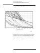
Agilent/HP 8644B Frequency Limits
Agilent/HP 8644B Frequency Limits
Agilent/HP 8644B
Mode Keys
• The [Mode 1] key provides the maximum FM deviation and minimum
RF output switching time. Noise level is highest in this mode, as shown
in the following table.
• The [Mode 2] key provides a median range of FM deviation and RF
output switching time, as shown in the following table.
• The [Mode 3] key provides the lowest noise level at the RF output, FM
deviation bandwidth is narrower, and the RF switching time is slower
than in either Modes 1 or 2.
Table 18-3 Agilent/HP 8644B Frequency Limits
Note: Special Function 120 must be enabled for DCFM
1
Minimum Recommended PTR (Peak Tune Range)
PTR =FM Deviation x VTR
Model
Numbe
r
Option
Band
Minimum
(MHz)
Band
Maximum
(MHz)
Mode 3 Mode 2 Mode 1
8644B 002 1030 2060 200000 2000000 20000000
8644B 002 515 1029.99999999 100000 1000000 10000000
8644B Standar
d
515 1030 100000 1000000 10000000
8644B Both 257.5 514.99999999 50000 500000 5000000
8644B Both 128.75 257.49999999 25000 250000 2500000
8644B Both 64.375 128.74999999 12500 125000 1250000
8644B Both 32.1875 64.37499999 6250 62500 625000
8644B Both 16.09375 32.18749999 3120 31200 312000
8644B Both 8.046875 16.09374999 1560 15600 156000
8644B Both 4.0234375 8.04687499 781 7810 78100
8644B Both 2.01171875 4.02343749 390 3900 39000
8644B Both 1.005859375 2.01171874 195 1950 19500
8644B Both 0.5029296875 1.005859365 97.6 976 9760
8644B Both 0.25146484375 0.5029296775 48.8 488 4880
1
Takes into account limited tuning resolution available in linear FM (Special Function 120, refer to “How to Access Special
Functions” on page 18-15).