
User`s guide


Agilent Technologies E5500 Phase Noise Measurement System
7-71
Absolute Measurement Examples
RF Synthesizer using DCFM
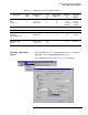
5 Test Set Tab
Input Attenuation
LNA Low Pass Filter
•LNAGain
•DCBlock
• PLL Integrator Attenuation
•0dB
• 20 MHz (Auto checked)
• Auto Gain (Minimum Auto Gain - 14 dB)
• Not checked
•0dBm
6 Downconverter Tab • The downconverter parameters do not apply to this
measurement example.
7GraphTab
•Title
• Graph Type
• X Scale Minimum
• X Scale Maximum
• Y Scale Minimum
• Y Scale Maximum
• Normalize trace data to a:
• Scale trace data to a new
carrier frequency of:
• Shift trace data DOWN by:
• Trace Smoothing Amount
• Power present at input of DUT
• RF Synthesizer vs Agilent/HP 8663A using DCFM
• Single-sideband Noise (dBc/Hz)
•10Hz
•4E+6Hz
•0dBc/Hz
• - 170 dBc/Hz
• 1 Hz bandwidth
• 1 times the current carrier frequency
•0dB
•0
•0dB
Table 7-12 Parameter Data for the RF Synthesizer (DCFM) Measurement
Step Parameters Data