
User`s guide


Contact Mode Imaging 5
Agilent 5500 SPM User’s Guide 97
changes in tip deflection in order to maintain constant force. 10 % is
a good starting value; more information on optimizing the gains is
in“Gains" on page 101.
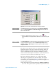
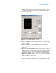
15 In the Scan and Motor window, select the Scan tab (Figure 68).
Figure 68 Scan and Motor window: Scan tab
16 Enter a scan Speed, stated in Lines/Second (ln/s). A typical starting
value is 1-2 ln/s.
17 Select a resolution from the X list. 256 is a good starting value,
providing ~11 nm/pixel resolution for the 3 micron scan size selected
in Figure 68.
18 The grid in the Scan and Motor window shows the range of motion
of the X and Y piezo actuators. The yellow square represents the size
and location of the scan, based on the current scan settings. Change
the Size (in microns) to set the scan size in both X and Y. Enter X
Offset and/or Y Offset values to move the scan region. You can also
click and drag the yellow box to move the region. Click the “+”
button to return the offsets to zero.
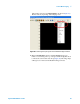
19 In the Realtime Images window, choose to display Topography,
Deflection and Friction. Click the “+” button of the window to add a
buffer. To set what each buffer will display, right-click inside the