
User`s guide


MAC III Mode 11
Agilent 5500 SPM User’s Guide 187
the box to replace the Ref Set value with the lock-in
signal.
Select Sum plus GND to pass the Ref Set value from
the AFM controller directly to the microscope.
These are the default settings.
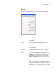
BNC 1 and 2 Each of the Lock-ins includes seven output
channels: Deflection, Friction, SP and AUX 1-4.
These output signals are routed to the AFM
controller. They can also be duplicated at the two
BNC connectors on the MAC III controller for
additional routing flexibility.
By default, Deflection is routed to BNC1, and
Friction is routed to BNC2. The actual signal sent to
the BNC connectors is selected in the Output
Channels, described next.
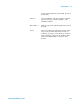
Outputs The MAC III controller includes seven outputs
(Deflection, Friction, SP, AUX 1-4) that are routed
to the AFM controller for imaging.
Each output can carry one of thirteen signals: the
Amplitude, Phase, X Component or Y Component
of the three lock-in signals; or the output of the
MAC III internal servo. Selecting GND for any
output sets its output to 0.
By default, the Deflection output carries Amplitude
1 (the amplitude of Lock-in 1 output). The Friction
output carries Phase 1. The remaining outputs are
set to GND.
Select the Pass Through check box for each output
to pass the signal directly from the microscope to the
AFM controller without further contribution from
the MAC III controller. By default, Pass Through is
selected for each output.
NOTE
In KFM Mode, the SP (Scanning Potential) channel is set to Servo Output
and the Pass Through box is not selected. The Servo Output is the DC
bias produced by the servo to counteract the sample bias.