
User`s guide


MAC III Mode 11
Agilent 5500 SPM User’s Guide 186
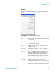
Drive Out Routes the output from one of the three lock-in
signals to the circuit controlling oscillation of the
cantilever (either AAC or MAC, depending on your
setup). Set this option to GND to turn off the output
from the MAC III. The default value is Drive 1 (the
output from Lock-in 1).
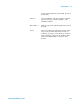
Sample Bias The Sample Bias is set in the Servo window and, by
default, is sent from the AFM controller to the
microscope. This option allows you to add the signal
from one of the MAC III lock-ins to the Sample
Bias, or to replace the Sample Bias completely.
(Either Tip Bias or Sample Bias is selected in the
Main tab).
First, select the Lock-in. Select the Sum check box
to add the Lock-in signal to the Sample Bias; clear
the box to replace the Sample Bias with the lock-in
signal.
Select Sum plus GND to pass the Sample Bias from
the AFM controller directly to the microscope.
These are the default settings.
Tip Bias The Tip Bias is also set under the Main tab of the
Servo window and, by default, sent from the AFM
controller to the microscope. The choice between
Tip or Sample bias is made under the Advanced tab
in the Servo window. This option allows you to add
the signal from one of the MAC III lock-ins to the
Tip Bias, or to replace the Tip Bias completely.
First, select the Lock-in. Select the Sum check box
to add the Lock-in signal to the Tip Bias; clear the
box to replace the Tip Bias with the lock-in signal.
Select Sum plus GND to pass the Tip Bias from the
AFM controller directly to the microscope. These
are the default settings.
Ref Set Ref Set is the set point for the electrochemistry
potentiostat.
First, select the Lock-in. Select the Sum check box
to add the Lock-in signal to the Ref Set value; clear