
User`s guide


MAC III Mode 11
Agilent 5500 SPM User’s Guide 180
Optimize Phase shifts the phase signal to maximize the X Component 2
(i.e., to maximize contrast).
X Component 2 and Phase 2 are routed to the Aux 1 and Aux 2 outputs,
respectively, for monitoring. To view changes in the EFM signal,
choose Aux 1 in the Realtime Images window.
KFM
In KFM Mode, Lock-in 1 is used to drive the cantilever, with the
Deflection channel as its Input. Lock-in 2 provides an AC tip bias, also
with the Deflection channel as its Input. A DC bias is provided by an
internal servo mechanism to counter vertical deflection of the tip.
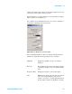
Choose Mode > KFM to open the KFM Controls window:
Figure 121 KFM Controls window
NOTE
For KFM mode, the Bias switch on the back of the Head Electronics Box
must be set to Tip.