
User`s guide


Additional Imaging Modes 7
Agilent 5500 SPM User’s Guide 118
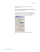
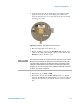
Figure 84 Servo window settings for STM imaging
10 Enter the Setpoint current, in nanoamps, that the system will try to
hold constant during scanning. A typical setting is 1-2 nA.
11 Enter the I and P gains for the z-servo, which will dictate how
quickly the system will adjust to changes in tunneling current.
Typical values are 1-2 % for both gains.
12 In the Realtime Images window choose to display images for
Current and Topography.
13 In the Scan and Motor window set the scan size, speed and offsets.
A scan Speed of 1 ln/s is a good starting value.
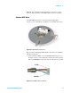
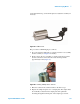
14 Using the Close switch on the HEB, raise the sample until the tip is
close to, but not touching, the scanner. The video system is not useful
in STM as the tip is essentially vertical, so view the tip from the side
of the microscope and bring it as close to the sample as you can. Be
certain to not drive the tip into the sample. To be safe you can make
the approach length longer, which will just add a little time to the
approach.
15 Click the Approach button in PicoView’s toolbar. The scanner will
lower until the Setpoint current is reached.
16 For lowest current operation, once engaged reduce the Setpoint value
until the indicator in the Servo window changes from green to red.
Then increase the Setpoint until the indicator in the Servo window
just turns green. For rougher surfaces you may need to increase the
setpoint current slightly more.
17 In the Scan and Motor window click the Up or Down arrows to
begin the scan.