
User`s guide


Additional Imaging Modes 7
Agilent 5500 SPM User’s Guide 117
5
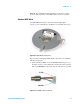
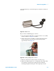
Attach an electrode from the sample plate to the sample. Lift the
spring-loaded electrode clip on the sample plate and insert the
electrode under it (Figure 83). Connect the electrode to the sample,
ensuring good contact.
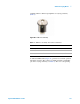
Figure 83 Sample on plate with electrode attached
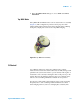
6 Place the sample plate on the microscope.
7 Plug the 3-pin EC connector of the EC/MAC cable into the 3-pin
socket on the sample plate. Plug the other end of the cable into the
EC/MAC socket on the microscope.
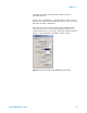
8 In PicoView, choose Mode > STM.
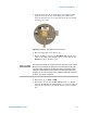
9 In the Servo window enter the Bias Voltage (Figure 84). Typical
values are 50-200 millivolts (0.05-0.200 V). A positive bias indicates
current flow from the tip to the sample, and vice versa for negative
bias.
NOTE
The sample plate cable can transfer low levels of vibration to the sample.
During very high resolution imaging this can affect images quality. We
recommend first plugging the sample plate cable to the flexible 3-wire
umbilical included with the sample plate. The umbilical should then be
plugged in to the microscope base. The umbilical’s individual wires tend
to reduce the transfer of vibration.