
User`s guide


10 User’s and Service Guide Supplement
E4438C Option HEC
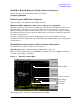
Repeatable Triggering for Multiple Baseband Sources
Trigger using External Clock
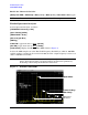
The following section introduces a technique using the internal baseband generator (phase
coherent with the external clock) that will allow < ± 0.5 ns timing resolution. By using the
internal Marker
1
functions, Event
1
output connectors, Pattern Trigger In connectors in the
standard arbitrary waveform generator, and designating one unit as the “Master” and the
other as the “Slave” unit, the overall jitter can be reduced to ± 0.5 ns or less. The Marker
function will output a transitional level that corresponds to a specific point of the sampled
waveform and an opposite transitional level corresponding to another specific point in the
sampled waveform. For instance, if the sampled waveform had 200 points and the first
point selected using Marker 1 was #10, and the second point selected was #50 then the
output at the Event 1 would show a transitional level starting at the 10
th
point and an
opposite transitional level at the 50
th
point. The transitional level is a 3.3 V CMOS high
output when positive polarity is selected and a 3.3 V CMOS low output when negative
polarity is selected.
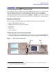
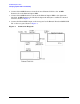
The “Master” unit will output on the Event 1 output connector and the “Slave” unit will be
triggered using the Pattern Trigger Input. This will insure that both units are
synchronized together with minimal jitter since the “Master” unit is using the external
clock as a reference signal through the Event 1/Pattern Trigger In to synchronize both
units. Insure that the External Clock used to synchronize the two E4438C Option HEC
units is stable. This will be the determining factor in the integrity of the ARB output
waveforms.
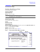
The expected frequency range of the External Clock is 200 MHz to 400 MHz. The E4438C
Option HEC sample rate is equal to the External Clock divided by 4. This means that if the
sample rate can be selected between the frequency range of 50 MHz and 100 MHz.
As mentioned in the previous section, each I/Q input has DACs that will settle on a
random state that may introduce errors into the measurement. The Align DAC function
will need to be utilized in both E4438C Option HEC units (Master then Slave) to insure
that each I/Q set is aligned to reduce any time skew. The following sections contain the
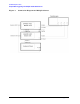
procedure to setup triggering using the external clock.
1. Refer to the E4438C User Guide regarding Marker Functions and Event 1 output connections.