
User`s guide


User’s and Service Guide Supplement 9
E4438C Option HEC
Repeatable Triggering for Multiple Baseband Sources
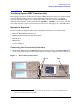
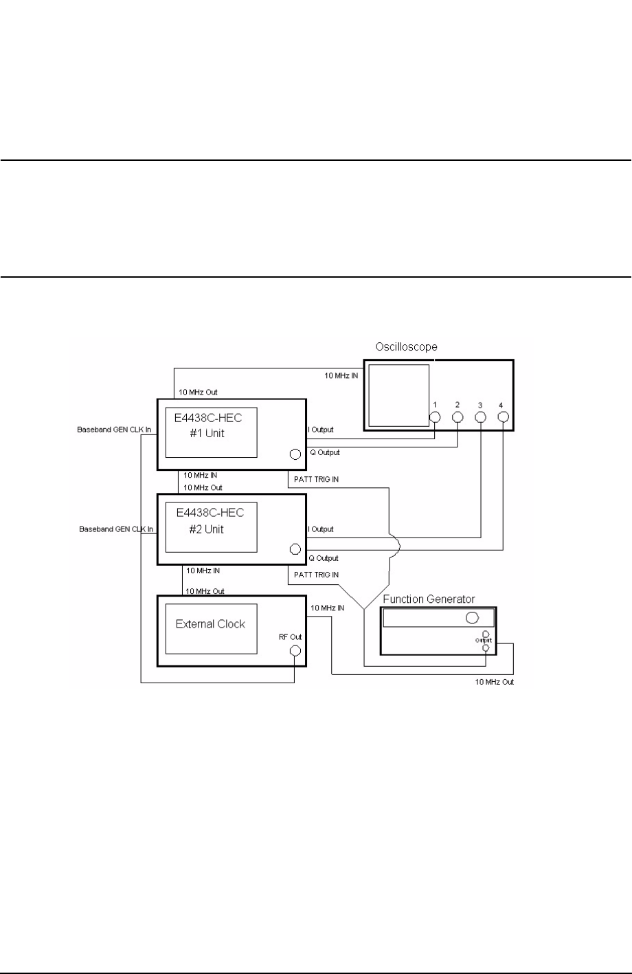
Trigger using Function Generator
External hardware is used to synchronize the trigger to the external clock. The
synchronized trigger is then split and routed to the Pattern Trigger Input of the ESG’s.
The trigger cable length must be the same.
NOTE
The external trigger signal is re-latched inside each ESG. This is not a
problem as long as the ESGs share a common clock and the input trigger does
not fall on a clock edge. It may be necessary to adjust the cable lengths to
insure that the synchronized external trigger does not fall on a clock edge
inside the ESGs. A trigger signal falling on a clock edge will be apparent by
10 ns (1/Sample rate) of jitter between the output signals.
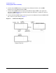
Figure 6 Function Generator
This approach connects a function generator to the Pattern Trigger Input on both sources
to achieve simultaneous triggering and a time-invariant output. Using the Pattern Trigger
Input can introduce approximately ± 10 ns of jitter due to the fact that the function
generator is not locked to the external clock input. Therefore the maximum combined jitter
of two or more sources is approximately ± 20 ns. As a result, one waveform will be shifting
in time relative to the other for each trigger event inside of this 20 ns window. This time
shift can be significantly improved if the function generator was phase coherent with the
reference clock. This would allow repeatable trigger latching across multiple sources.
Unfortunately most function generators use a PLL technique that allows the function
generator to be frequency locked but not phase coherent with the reference input.
Therefore slow phase drift will occur relative to the external reference clock.