
Programming instructions


Downloading and Using Files
User File Data Downloads
Chapter 4172
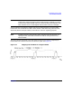
For this protocol configuration, the signal generator’s firmware loads PRAM with the bits
defined in the following table.
Event 1 output is set to 0 or 1 depending on the sync out selection, which enables the Event 1
output at either the beginning of the frame, beginning of a specific timeslot, or at all timeslots.
Frame Timeslot PRAM
Address
Data Bits Burst Bits Pattern
Reset Bit
1 0 0 -155 0/1 (don’t care) 0 (off) 0 (off)
1 1 (on) 156 - 311 set by GSM standard (42 bits)
& first 114 bits of user file
1 (on) 0
1 2 312 - 467 0/1 (don’t care) 0 0
1 3 468 - 624 0/1 (don’t care) 0 0
1 4 625 - 780 0/1 (don’t care) 0 0
1 5 781 - 936 0/1 (don’t care) 0 0
1 6 937 - 1092 0/1 (don’t care) 0 0
1 7 1093 - 1249 0/1 (don’t care) 0 0
2 0 1250 - 1405 0/1 (don’t care) 0 0
2 1 (on) 1406 - 1561 set by GSM standard (42 bits)
& remaining bits of user file
1 (on) 0
2 2 through
6
1562 - 2342 0/1 (don’t care) 0 0 (off)
2 7 2343 - 2499 0/1 (don’t care) 0 0
(1 in
address
2499 only)