
Programming instructions


Programming the Status Register System
Status Groups
Chapter 3126
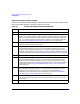
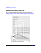
Data Questionable Condition Register
The Data Questionable Condition Register continuously monitors the hardware and firmware
status of the signal generator. Condition registers are read only.
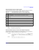
Table 3-7 Data Questionable Condition Register Bits
Bit Description
0, 1, 2 Unused. These bits are always set to 0.
3 Power (summary). This is a summary bit taken from the QUEStionable:POWer
register. A 1 in this bit position indicates that one of the following may have happened:
The ALC (Automatic Leveling Control) is unable to maintain a leveled RF output power
(i.e., ALC is UNLEVELED), the reverse power protection circuit has been tripped. See
the “Data Questionable Power Status Group” on page 129 for more information.
4 Temperature (OVEN COLD). A 1 in this bit position indicates that the internal
reference oscillator (reference oven) is cold.
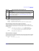
5
Frequency (summary). This is a summary bit taken from the
QUEStionable:FREQuency register. A 1 in this bit position indicates that one of the
following may have happened: synthesizer PLL unlocked, 10 MHz reference VCO PLL
unlocked, 1 GHz reference unlocked, sampler, YO loop unlocked or baseband 1 unlocked.
For more information, see the “Data Questionable Frequency Status Group” on page 132.
6 Unused. This bit is always set to 0.
7 Modulation (summary). This is a summary bit taken from the
QUEStionable:MODulation register. A 1 in this bit position indicates that one of the
following may have happened: modulation source 1 underrange, modulation source 1
overrange, modulation source 2 underrange, modulation source 2 overrange, modulation
uncalibrated. See the “Data Questionable Modulation Status Group” on page 135 for
more information.
8 Calibration (summary). This is a summary bit taken from the
QUEStionable:CALibration register. A 1 in this bit position indicates that one of the
following may have happened: an error has occurred in the DCFM/DCΦM zero
calibration, an error has occurred in the I/Q calibration. See the “Data Questionable
Calibration Status Group” on page 138 for more information.
9 Self Test. A 1 in this bit position indicates that a self-test has failed during power-up.
This bit can only be cleared by cycling the signal generator’s line power. *CLS will not
clear this bit.
10, 11 Unused. These bits are always set to 0.