Programming Guide Agilent Technologies ESG Vector Signal Generator This guide applies to signal generator models and associated serial number prefixes listed below. Depending on your firmware revision, signal generator operation may vary from descriptions in this guide. E4438C: US4146 Part Number: E4400-90505 Printed in USA April 2002 © Copyright 2001, 2002 Agilent Technologies, Inc.
Notice The material contained in this document is provided “as is”, and is subject to being changed, without notice, in future editions. Further, to the maximum extent permitted by applicable law, Agilent disclaims all warranties, either express or implied with regard to this manual and to any of the Agilent products to which it pertains, including but not limited to the implied warranties of merchantability and fitness for a particular purpose.
Contents 1. Getting Started . . . . . . . . . . . . . . . . . . . . . . . . . . . . . . . . . . . . . . . . . . . . . . . . . . . 1 Introduction to Remote Operation . . . . . . . . . . . . . . . . . . . . . . . . . . . . . . . . . . . . . . . . . . 2 Interfaces. . . . . . . . . . . . . . . . . . . . . . . . . . . . . . . . . . . . . . . . . . . . . . . . . . . . . . . . . . . . . 3 I/O Libraries . . . . . . . . . . . . . . . . . . . . . . . . . . . . . . . . . . . . . . . . . . . . . . . . . . . . . . . . .
Contents Queries Using Agilent BASIC . . . . . . . . . . . . . . . . . . . . . . . . . . . . . . . . . . . . . . . . . . . Queries Using NI-488.2 and C++. . . . . . . . . . . . . . . . . . . . . . . . . . . . . . . . . . . . . . . . . Queries Using VISA and C. . . . . . . . . . . . . . . . . . . . . . . . . . . . . . . . . . . . . . . . . . . . . . Generating a CW Signal Using VISA and C . . . . . . . . . . . . . . . . . . . . . . . . . . . . . . . .
Contents Baseband Operation Status Group . . . . . . . . . . . . . . . . . . . . . . . . . . . . . . . . . . . . . . Data Questionable Status Group . . . . . . . . . . . . . . . . . . . . . . . . . . . . . . . . . . . . . . . . Data Questionable Power Status Group . . . . . . . . . . . . . . . . . . . . . . . . . . . . . . . . . . Data Questionable Frequency Status Group . . . . . . . . . . . . . . . . . . . . . . . . . . . . . . Data Questionable Modulation Status Group. . . . . . . . . . . . . . . . . . .
Contents Downloading in Block Format . . . . . . . . . . . . . . . . . . . . . . . . . . . . . . . . . . . . . . . . . . Modulating and Activating the Carrier. . . . . . . . . . . . . . . . . . . . . . . . . . . . . . . . . . . Viewing the PRAM Waveform . . . . . . . . . . . . . . . . . . . . . . . . . . . . . . . . . . . . . . . . . . Data Transfer Troubleshooting . . . . . . . . . . . . . . . . . . . . . . . . . . . . . . . . . . . . . . . . . . . Direct PRAM Download Problems . . . . . . . . . . . . . .
1 Getting Started 1
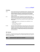
Getting Started Introduction to Remote Operation Introduction to Remote Operation ESG signal generators support the following interfaces: • General Purpose Interface Bus (GPIB) • Local Area Network (LAN) • ANSI/EIA232 (RS-232) serial connection Each of these interfaces, in combination with an I/O library and programming language, can be used to remotely control your signal generator.
Getting Started Introduction to Remote Operation Interfaces GPIB GPIB is used extensively when a dedicated computer is available for remote control of each instrument or system. Data transfer is fast because the GPIB handles information in 8-bit bytes. GPIB is physically restricted by the location and distance between the instrument/system and the computer; cables are limited to an average length of two meters per device with a total length of 20 meters.
Getting Started Introduction to Remote Operation Programming Language The programming language is used along with Standard Commands for Programming Instructions (SCPI) and I/O library functions to remotely control the signal generator. Common programming languages include: • C/C++ • Agilent BASIC • LabView • Java • Visual Basic ® Java is a U.S. trademark of Sun Microsystems, Inc.
Getting Started Using GPIB Using GPIB The GPIB allows instruments to be connected together and controlled by a computer. The GPIB and its associated interface operations are defined in the ANSI/IEEE Standard 488.1-1987 and ANSI/IEEE Standard 488.2-1992. See the IEEE website, www.ieee.org, for details on these standards. 1. Installing the GPIB Interface Card A GPIB interface card must be installed in your computer.
Getting Started Using GPIB Table 1-2 NI-GPIB Interface Card for PC-Based Systems Interface Card Operating System I/O Library Languages Backplane /BUS Max I/O National Instrument’s PCI-GPIB Windows 95/98/2000/ ME/NT VISA NI-488.2 C/C++, Visual BASIC, LabView PCI 32 bit 1.5 Mbytes/s National Instrument’s PCI-GPIB+ Windows NT VISA NI-488.2 C/C++, Visual BASIC, LabView PCI 32 bit 1.5 Mbytes/s NI-488.
Getting Started Using GPIB 2. Selecting I/O Libraries for GPIB The I/O libraries are included with your GPIB interface card. These libraries can also be downloaded from the National Instruments website or the Agilent website. The following is a discussion on these libraries. VISA VISA is an I/O library used to develop I/O applications and instrument drivers that comply with industry standards. It is recommended that the VISA library be used for programming the signal generator.
Getting Started Using GPIB Table 1-4 Agilent GPIB Cables Model 10833A 10833B 10833C 10833D 10833F 10833G Length 1 meter 2 meters 4 meters .5 meter 6 meters 8 meters 4. Verifying GPIB Functionality Use the VISA Assistant, available with the Agilent IO Library or the Getting Started Wizard available with the National Instrument I/O Library, to verify GPIB functionality. These utility programs allow you to communicate with the signal generator and verify its operation over the GPIB.
Getting Started Using GPIB GPIB Function Statements Function statements are the basis for GPIB programming and instrument control. These function statements combined with SCPI provide management and data communication for the GPIB interface and the signal generator. This section describes functions used by different I/O libraries. Refer to the NI-488.2 Function Reference Manual for Windows, Agilent Standard Instrument Control Library reference manual, and Microsoft® Visual C++ 6.
Getting Started Using GPIB Remote Function The Agilent BASIC function REMOTE and the other listed I/O library functions cause the signal generator to change from local operation to remote operation. In remote operation, the front panel keys are disabled except for the Local key and the line power switch. Pressing the Local key on the signal generator front panel restores manual operation. Table 1-6 Agilent BASIC VISA NI-488.
Getting Started Using GPIB VISA Library NI-488.2 Library SICL The VISA library, at this time, does not have a similar command. The NI-488.2 library function places the instrument described in the parameter list in remote mode by asserting the Remote Enable (REN) GPIB line. The lockout state is then set using the Local Lockout (LLO) GPIB message. Local control can be restored only with the EnableLocal NI-488.2 routine or hard reset. The parameter list describes the interface or device descriptor.
Getting Started Using GPIB Clear Function The Agilent BASIC function CLEAR and the other listed I/O library functions cause the signal generator to assume a cleared condition. Table 1-9 Agilent BASIC VISA NI-488.
Getting Started Using GPIB send. NI-488.2 Library SICL The NI-488.2 library function addresses the GPIB and writes data to the signal generator. The parameter list includes the instrument address, session id, and the data to send. The Agilent SICL function converts data using the format string. The format string specifies how the argument is converted before it is output. The function sends the characters in the format string directly to the instrument.
Getting Started Using LAN Using LAN The signal generator can be remotely programmed via a LAN interface and LAN-connected computer using one of several LAN interface protocols. The LAN allows instruments to be connected together and controlled by a LAN-based computer. LAN and its associated interface operations are defined in the IEEE 802.2 standard. See the IEEE website for more details.
Getting Started Using LAN 2. Setting Up the LAN Interface For LAN operation, an IP address must be assigned to the signal generator and the signal generator connected to the LAN. Your system administrator can issue a hostname, IP address, default gateway, and subnet mask for the signal generator. 1. Press Utility > GPIB/RS-232 LAN > LAN Setup. 2. Press Hostname. 3. Use the labeled text softkeys and/or numeric keypad to enter the desired hostname.
Getting Started Using LAN 3. Verifying LAN Functionality Verify the communications link between the computer and the signal generator remote file server using the ping utility. Compare your ping response to those described in Table 1-12. From a UNIX ® workstation, type: ping hostname 64 10 where hostname is your instruments name and 64 is the packet size, and 10 is the number of packets transmitted. Type man ping at the UNIX prompt for details on the ping command.
Getting Started Using LAN Table 1-12 Ping Responses Normal Response for UNIX A normal response to the ping command will be a total of 9 or 10 packets received with a minimal average round-trip time. The minimal average will be different from network to network. LAN traffic will cause the round-trip time to vary widely. Normal Response for DOS or Windows A normal response to the ping command will be a total of 9 or 10 packets received if 10 echo requests were specified.
Getting Started Using LAN Using VXI-11 The signal generator supports the LAN interface protocol described in the VXI-11 standard. VXI-11 is an instrument control protocol based on Open Network Computing/Remote Procedure Call (ONC/RPC) interfaces running over TCP/IP. It is intended to provide GBIB capabilities such as SRQ (Service Request), status byte reading, and DCAS (Device Clear State) over a LAN interface.
Getting Started Using LAN Figure 1-2 Chapter 1 Show Devices Form 19
Getting Started Using LAN Using Sockets LAN Sockets LAN is a method used to communicate with the signal generator over the LAN interface using the Transmission Control Protocol/ Internet Protocol (TCP/IP). A socket is a fundamental technology used for computer networking and allows applications to communicate using standard mechanisms built into network hardware and operating systems.
Getting Started Using LAN Using TELNET LAN TELNET provides a means of communicating with the signal generator over the LAN. The TELNET client, run on a LAN connected computer, will create a login session on the signal generator. A connection, established between computer and signal generator, generates a user interface display screen with SCPI> prompts on the command line. Using the TELNET protocol to send commands to the signal generator is similar to communicating with the signal generator over GPIB.
Getting Started Using LAN Figure 1-3 Connect Form Using TELNET On a PC With a Host/Port Setting Menu GUI 1. On your PC click Start > Run. 2. Type telnet then click the Ok button. The TELNET connection screen will be displayed. 3. Click on the Connect menu then select Remote System. A connection form will be displayed. Refer to Figure 1-3. 4. Enter the hostname, port number, and TermType then click Connect. Refer to Figure 1-3.
Getting Started Using LAN Figure 1-4 TELNET Window The Standard UNIX TELNET Command Synopsis telnet [host [port]] Description This command is used to communicate with another host using the TELNET protocol. When the command telnet is invoked with host or port arguments, a connection is opened to the host, and input is sent from the user to the host. Options and Parameters The command telnet operates in character-at-a-time or line-by-line mode. In line-by-line mode, typed text is echoed to the screen.
Getting Started Using LAN NOTE If your TELNET connection is in line-by-line mode, there is no local echo. This means you cannot see the characters you are typing until you press the Enter key. To remedy this, change your TELNET connection to character-by-character mode. Escape out of TELNET and, at the telnet> prompt, type mode char. If this does not work, consult your TELNET program’s documentation.
Getting Started Using LAN Using FTP FTP allows users to transfer files between the signal generator and any computer connected to the LAN. For example, you can use FTP to download instrument screen images to a computer or download files to the signal generator. When logged onto the signal generator with the FTP command, the signal generator’s file structure can be accessed. Figure 1-5 shows the FTP interface and lists the directories in the signal generator’s user level directory.
Getting Started Using LAN 4. At the password prompt, press enter. You are now in the signal generator’s user directory. Typing help at the command prompt will show you the FTP commands that are available on your system. 5. Type quit or bye to end your FTP session. 6. Type exit to end the command prompt session.
Getting Started Using RS-232 Using RS-232 The RS-232 serial interface can be used to communicate with the signal generator. The RS-232 connection is standard on most PCs and can be connected to the signal generator’s rear-panel connector using the cable described in Table 1-13 on page 28. Many functions provided by GPIB, with the exception of indefinite blocks, serial polling, GET, non-SCPI remote languages, and remote mode are available using the RS-232 interface.
Getting Started Using RS-232 2. Setting Up the RS-232 Interface 1. Press Utility > GPIB/RS-232 LAN> RS-232 Setup > RS-232 Baud Rate > 9600 Use baud rates 57600 or lower only. Select the signal generator’s baud rate to match the baud rate of your computer or UNIX workstation or adjust the baud rate settings on your computer to match the baud rate setting of the signal generator. NOTE The default baud rate for VISA is 9600. This baud rate can be changed with the “VI_ATTR_ASRL_BAUD” VISA attribute. 2.
Getting Started Using RS-232 3. Verifying RS-232 Functionality You can use the HyperTerminal program available on your computer to verify the RS-232 interface functionality. To run the HyperTerminal program, connect the RS-232 cable between the computer and the signal generator and perform the following steps: 1. On the PC click Start > Programs > Accessories > HyperTerminal. 2. Select HyperTerminal. 3. Enter a name for the session in the text box and select an icon. 4.
Getting Started Using RS-232 Agilent Technologies , US40000001,C.02.00 Character Format Parameters The signal generator uses the following character format parameters when communicating via RS-232: • Character Length: Eight data bits are used for each character, excluding start, stop, and parity bits. • Parity Enable: Parity is disabled (absent) for each character. • Stop Bits: One stop bit is included with each character. If You Have Problems 1.
2 Programming Examples 31
Programming Examples Using the Programming Examples Using the Programming Examples The programming examples for remote control of the signal generator use the GPIB, LAN, and RS-232 interfaces and demonstrate instrument control using different I/O libraries and programming languages. Many of the example programs in this chapter are interactive; the user will be prompted to perform certain actions or verify signal generator operation or functionality.
Programming Examples Using the Programming Examples • C/C++ programming language with the Microsoft Visual C++ 6.0 IDE • National Instruments PCI- GPIB interface card or Agilent GPIB interface card • National Instruments VISA Library or Agilent VISA library • COM1 or COM2 serial port available • LAN interface card The Agilent BASIC examples were run on a UNIX 700 Series workstation.
Programming Examples GPIB Programming Examples GPIB Programming Examples • “Interface Check using Agilent BASIC” on page 35 • “Interface Check Using NI-488.2 and C++” on page 36 • “Interface Check using VISA and C” on page 37 • “Local Lockout Using Agilent BASIC” on page 38 • “Local Lockout Using NI-488.2 and C++” on page 39 • “Queries Using Agilent BASIC” on page 41 • “Queries Using NI-488.
Programming Examples GPIB Programming Examples Interface Check using Agilent BASIC This simple program causes the signal generator to perform an instrument reset. The SCPI command *RST places the signal generator into a pre-defined state and the remote annunciator (R) appears on the front panel display. The following program example is available on the ESG Documentation CD-ROM as basicex1.txt.
Programming Examples GPIB Programming Examples Interface Check Using NI-488.2 and C++ This example uses the NI-488.2 library to verify that the GPIB connections and interface are functional. Launch Microsoft Visual C++ 6.0, add the required files, and enter the following code into your .cpp source file. The following program example is available on the ESG Documentation CD-ROM as niex1.cpp.
Programming Examples GPIB Programming Examples Interface Check using VISA and C This program uses VISA library functions and the C language to communicate with the signal generator. The program verifies that the GPIB connections and interface are functional. Launch Microsoft Visual C++ 6.0, add the required files, and enter the following code into your .cpp source file. The following program example is available on the ESG Documentation CD-ROM as visaex1.cpp.
Programming Examples GPIB Programming Examples Local Lockout Using Agilent BASIC This example demonstrates the Local Lockout function. Local Lockout disables the front panel signal generator keys. The following program example is available on the ESG Documentation CD-ROM as basicex2.txt. 10 !************************************************************************* 20 ! 30 ! PROGRAM NAME: basicex2.
Programming Examples GPIB Programming Examples Local Lockout Using NI-488.2 and C++ This example uses the NI-488.2 library to set the signal generator local lockout mode. Launch Microsoft Visual C++ 6.0, add the required files, and enter the following code into your .cpp source file. The following program example is available on the ESG Documentation CD-ROM as niex2.cpp. // // // // // // // // ************************************************************************************ PROGRAM NAME: niex2.
Programming Examples GPIB Programming Examples cout<
Programming Examples GPIB Programming Examples Queries Using Agilent BASIC This example demonstrates signal generator query commands. The signal generator can be queried for conditions and setup parameters. Query commands are identified by the question mark as in the identify command *IDN? The following program example is available on the ESG Documentation CD-ROM as basicex3.txt.
Programming Examples GPIB Programming Examples 420 430 440 450 460 470 480 490 500 510 520 530 540 550 560 570 580 42 END IF OUTPUT Sig_gen;"*IDN?" ! Querys for signal generator ID ENTER Sig_gen;C$ ! Enter in the signal generator ID ! Print the signal generator ID to the controller display PRINT PRINT "This signal generator is a ";C$ PRINT ! The next command is a query for the signal generator’s GPIB address OUTPUT Sig_gen;"SYST:COMM:GPIB:ADDR?" ENTER Sig_gen;D$ ! Enter in the signal generator’s address !
Programming Examples GPIB Programming Examples Queries Using NI-488.2 and C++ This example uses the NI-488.2 library to query different instrument states and conditions. Launch Microsoft Visual C++ 6.0, add the required files, and enter the following code into your .cpp source file. The following program example is available on the ESG Documentation CD-ROM as niex3.cpp. //************************************************************************************* // PROGRAM NAME: niex3.
Programming Examples GPIB Programming Examples cin.ignore(10000,’\n’); ibwrt(sig, ":FREQ:MODE?",11); // Querys source frequency mode ibrd(sig, rdVal,100); // Enters in the source frequency mode rdVal[ibcntl] = ’\0’; // Null character indicating end of array cout<<"Source frequency mode is "<
Programming Examples GPIB Programming Examples Queries Using VISA and C This example uses VISA library functions to query different instrument states and conditions. Launch Microsoft Visual C++ 6.0, add the required files, and enter the following code into your .cpp source file. The following program example is available on the ESG Documentation CD-ROM as visaex3.cpp. //**************************************************************************************** // PROGRAM FILE NAME:visaex3.
Programming Examples GPIB Programming Examples getch(); viPrintf(vi, "POW:AMPL?\n"); viScanf(vi, "%t", rdBuffer); // Querys the power level // Reads the response into rdBuffer // Prints the source power level printf("Source power (dBm) is : %s\n", rdBuffer); printf("Press any key to continue\n"); printf("\n"); // Prints new line character to the display getch(); viPrintf(vi, "FREQ:MODE?\n"); // Querys the frequency mode viScanf(vi, "%t", rdBuffer); // Reads the response into rdBuffer // Prints the source f
Programming Examples GPIB Programming Examples Generating a CW Signal Using VISA and C This example uses VISA library functions to control the signal generator. The signal generator is set for a CW frequency of 500 kHz and a power level of −2.3 dBm. Launch Microsoft Visual C++ 6.0, add the required files, and enter the code into your .cpp source file. The following program example is available on the ESG Documentation CD-ROM as visaex4.cpp.
Programming Examples GPIB Programming Examples viPrintf(vi, "POW:AMPL -2.3 dBm\n"); // Set the power level to -2.
Programming Examples GPIB Programming Examples Generating an Externally Applied AC-Coupled FM Signal Using VISA and C In this example, the VISA library is used to generate an ac-coupled FM signal at a carrier frequency of 700 MHz, a power level of −2.5 dBm, and a deviation of 20 kHz. Before running the program: • Connect the output of a modulating signal source to the signal generator’s EXT 2 input connector. • Set the modulation signal source for the desired FM characteristics.
Programming Examples GPIB Programming Examples printf("for an AC-coupled FM signal\n"); printf("Press any key to continue\n"); printf("\n"); getch(); printf("\n"); viPrintf(vi, viPrintf(vi, viPrintf(vi, viPrintf(vi, viPrintf(vi, viPrintf(vi, viPrintf(vi, viPrintf(vi, "*RST\n"); "FM:SOUR EXT2\n"); "FM:EXT2:COUP AC\n"); "FM:DEV 20 kHz\n"); "FREQ 700 MHz\n"); "POW:AMPL -2.
Programming Examples GPIB Programming Examples Generating an Internal AC-Coupled FM Signal Using VISA and C In this example the VISA library is used to generate an ac-coupled internal FM signal at a carrier frequency of 900 MHz and a power level of −15 dBm. The FM rate will be 5 kHz and the peak deviation will be 100 kHz. Launch Microsoft Visual C++ 6.0, add the required files, and enter the following code into your .cpp source file.
Programming Examples GPIB Programming Examples viPrintf(vi, "FREQ 900 MHz\n"); viPrintf(vi, "POW -15 dBm\n"); viPrintf(vi, "FM2:STAT ON\n"); viPrintf(vi, "OUTP:STAT ON\n"); printf("\n"); // // // // // // Sets carrier frequency to 700 MHz Sets the power level to -2.
Programming Examples GPIB Programming Examples Generating a Step-Swept Signal Using VISA and C In this example the VISA library is used to set the signal generator for a continuous step sweep on a defined set of points from 500 MHz to 800 MHz. The number of steps is set for 10 and the dwell time at each step is set to 500 ms. The signal generator will then be set to local mode which allows the user to make adjustments from the front panel. Launch Microsoft Visual C++ 6.
Programming Examples GPIB Programming Examples viPrintf(vi, "INIT:CONT ON\n"); // Begins the step sweep operation // Print user information printf("The signal generator is in step sweep mode. The frequency range is\n"); printf("500 to 800 mHz. There is a .5 sec dwell time at each 30 mHz step.
Programming Examples GPIB Programming Examples Saving and Recalling States Using VISA and C In this example, instrument settings are saved in the signal generator’s save register. These settings can then be recalled separately; either from the keyboard or from the signal generator’s front panel. Launch Microsoft Visual C++ 6.0, add the required files, and enter the following code into your .cpp source file. The following program example is available on the ESG Documentation CD-ROM as visaex8.cpp.
Programming Examples GPIB Programming Examples printf("used to save and recall an instrument’s state\n"); printf("\n"); viPrintf(vi, "*RST\n"); // Resets the signal generator viPrintf(vi, "FREQ 5 MHz\n"); // Sets sig gen frequency viPrintf(vi, "POW:ALC OFF\n"); // Turns ALC Off viPrintf(vi, "POW:AMPL -3.2 dBm\n"); // Sets power for -3.
Programming Examples GPIB Programming Examples Reading the Data Questionable Status Register Using VISA and C In this example, the signal generator’s data questionable status register is read. You will be asked to set up the signal generator for error generating conditions. The data questionable status register will be read and the program will notify the user of the error condition that the setup caused. Follow the user prompts presented when the program runs. Launch Microsoft Visual C++ 6.
Programming Examples GPIB Programming Examples viClear(vi); // Clears the signal generator // Prints user information printf("Programming example to demonstrate reading the signal generator’s Status Byte\n"); printf("\n"); printf("Manually set up the sig gen for an unleveled output condition:\n"); printf("* Set signal generator output amplitude to +20 dBm\n"); printf("* Set frequency to maximum value\n"); printf("* Turn On signal generator’s RF Output\n"); printf("* Check signal generator’s display for the
Programming Examples GPIB Programming Examples printf("Press Enter when ready\n"); printf("\n"); getch(); // Waits for keyboard user input viPrintf(vi, "STAT:QUES:MOD:ENAB 16\n"); // Enables the Data Questionable // Modulation Condition Register // bits ’0’,’1’,’2’,’3’ and ’4’ viPrintf(vi, "STAT:QUES:MOD:COND?\n"); // Querys the register for any // set bits viScanf(vi, "%s", rdBuffer); // Reads the decimal sum of the // set bits num=(int (rdBuffer[1]) -(’0’)); // Converts string data to numeric switch (num)
Programming Examples GPIB Programming Examples Reading the Service Request Interrupt (SRQ) Using VISA and C This example demonstrates use of the Service Request (SRQ) interrupt. By using the SRQ, the computer can attend to other tasks while the signal generator is busy performing a function or operation. When the signal generator finishes it’s operation, or detects a failure, then a Service Request can be generated.
Programming Examples GPIB Programming Examples ViStatus viStatus = 0; char rdBuffer[MAX_CNT]; // Declares a variable of type ViStatus // for GPIB verifications // Declare a block of memory data viStatus=viOpenDefaultRM(&defaultRM);// Initialize VISA session if(viStatus < VI_SUCCESS){ // If problems, then prompt user printf("ERROR initializing VISA...
Programming Examples GPIB Programming Examples viStatus = viInstallHandler(vi, VI_EVENT_SERVICE_REQ, interupt, rdBuffer); // The next line of code enables the // detection of an event viStatus = viEnableEvent(vi, VI_EVENT_SERVICE_REQ, VI_HNDLR, VI_NULL); viPrintf(vi, "FREQ:MODE LIST\n");// Sets frequency mode to list viPrintf(vi, "LIST:TYPE STEP\n");// Sets sweep to step viPrintf(vi, "LIST:TRIG:SOUR IMM\n");// Immediately trigger the sweep viPrintf(vi, "LIST:MODE AUTO\n");// Sets mode for the list sweep viP
Programming Examples GPIB Programming Examples viClose(event); return VI_SUCCESS; // Closes the event } Chapter 2 63
Programming Examples LAN Programming Examples LAN Programming Examples • “VXI-11 Programming Using SICL and C” on page 65 • “VXI-11 Programming Using VISA and C” on page 66 • “Setting Parameters and Sending Queries Using Sockets and C” on page 72 • “Setting the Power Level and Sending Queries Using PERL” on page 89 • “Generating a CW Signal Using Java” on page 91 The LAN programming examples in this section demonstrate the use of VXI-11 and Sockets LAN to control the signal generator.
Programming Examples LAN Programming Examples VXI-11 Programing The signal generator supports the VXI-11 standard for instrument communication over the LAN interface. Agilent IO Libraries support the VXI-11 standard and must be installed on your computer before using the VXI-11 protocol. Refer to “Using VXI-11” on page 18 of this Programming Guide for information on configuring and using the VXI-11 protocol. The VXI-11 examples use TCPIP0 as the board address.
Programming Examples LAN Programming Examples char buf[256]; ionerror(I_ERROR_EXIT); // Variable for id string // Register SICL error handler // Open SICL instrument handle using VXI-11 protocol sprintf(instNameBuf, "lan[%s]:inst0", instrumentName); id = iopen(instNameBuf); // Open instrument session itimeout(id, 1000); // Set 1 second timeout for operations printf("Setting frequency to 1 Ghz...\n"); iprintf(id, "freq 1 GHz\n"); // Set frequency to 1 GHz printf("Waiting for source to settle...
Programming Examples LAN Programming Examples // screen. Next the signal generator is set for a -5 dBm power level and then // queried for the power level. The power level is printed to the screen. // // IMPORTANT: Set up the LAN Client using the IO Config utility // //**************************************************************************************** #include #include #include #include #include "StdAfx.h"
Programming Examples LAN Programming Examples status = viRead(instr, (ViBuf)buffer, MAX_COUNT, &retCount); buffer[retCount]= ’\0’; // Indicate the end of the string printf("Power level = "); // Print header to the screen printf(buffer); // Print the queried power level printf("\n"); status = viClose(instr); // Close down the system status = viClose(defaultRM); return 0; } 68 Chapter 2
Programming Examples LAN Programming Examples Sockets LAN Programming using C The program listing shown in “Setting Parameters and Sending Queries Using Sockets and C” on page 72 consists of two files; lanio.c and getopt.c. The lanio.c file has two main functions; int main() and an int main1(). The int main() function allows communication with the signal generator interactively from the command line. The program reads the signal generator's hostname from the command line, followed by the SCPI command.
Programming Examples LAN Programming Examples The program will run and output a sequence of SCPI commands to the signal generator. The UNIX display will show a display similar to the following: unix machine: /users/mydir $ ./lanio ID: Agilent Technologies, E4438C, US70000001, C.02.00 Frequency: +2.5000000000000E+09 Power Level: -5.00000000E+000 Sockets on Windows In Windows, the routines send() and recv() must be used, since fread() and fwrite() may not work on sockets.
Programming Examples LAN Programming Examples Programming Using main1() Function. The int main1() function will output a sequence of commands in a program format. If you want to run a program using a sequence of commands then perform the following: 1. Enter the hostname of your signal generator in the openSocket function of the main1() function of the lanio.cpp program. 2. Rename the lanio.cpp int main1() function to int main() and the original int main() function to int main1(). 3.
Programming Examples LAN Programming Examples Setting Parameters and Sending Queries Using Sockets and C The following programming examples are available on the ESG Documentation CD-ROM as lanio.c and getopt.c. /*************************************************************************** * $Header: lanio.c 04/24/01 * $Revision: 1.1 $ * $Date: 10/24/01 * PROGRAM NAME: lanio.c * * $Description: Functions to talk to an Agilent signal generator * via TCP/IP. Uses command-line arguments.
Programming Examples LAN Programming Examples * routines typically use the lower level read() and write() calls. * * - In the Windows environment, file operations such as read(), write(), * and close() cannot be assumed to work correctly when applied to * sockets. Instead, the functions send() and recv() MUST be used. *****************************************************************************/ /* Support both Win32 and HP-UX UNIX environment */ #ifdef _WIN32 /* Visual C++ 6.
Programming Examples LAN Programming Examples # include
Programming Examples LAN Programming Examples /*************************************************************************** * > $Function: openSocket$ * * $Description: open a TCP/IP socket connection to the instrument $ * * $Parameters: $ * (const char *) hostname . . . . Network name of instrument. * This can be in dotted decimal notation. * (int) portNumber . . . . . . . The TCP/IP port to talk to. * Use 5025 for the SCPI port. * * $Return: (int) . . . . . . . . A file descriptor similar to open(1).
Programming Examples LAN Programming Examples peeraddr_in.sin_family = AF_INET; peeraddr_in.
Programming Examples LAN Programming Examples **************************************************************************/ char * recv_line(SOCKET sock, char * result, int maxLength) { #ifdef WINSOCK int cur_length = 0; int count; char * ptr = result; int err = 1; while (cur_length < maxLength) { /* Get a byte into ptr */ count = recv(sock, ptr, 1, 0); /* If no chars to read, stop. */ if (count < 1) { break; } cur_length += count; /* If we hit a newline, stop.
Programming Examples LAN Programming Examples } /*************************************************************************** * > $Function: queryInstrument$ * * $Description: send a SCPI command to the instrument, return a response.$ * * $Parameters: $ * (FILE *) . . . . . . . . . file pointer associated with TCP/IP socket. * (const char *command) . . SCPI command string. * (char *result) . . . . . . where to put the result. * (size_t) maxLength . . . . maximum size of result array in bytes.
Programming Examples LAN Programming Examples { if (ch == ’#’) { /* binary data encountered - figure out what it is */ long numDigits; long numBytes = 0; /* char length[10]; */ count = recv(sock, tmp_buf, 1, 0); /* read 1 char */ ch = tmp_buf[0]; if ((count < 1) || (ch == EOF)) break; /* End of file */ if (ch < ’0’ || ch > ’9’) break; numDigits = ch - ’0’; /* unexpected char */ if (numDigits) { /* read numDigits bytes into result string.
Programming Examples LAN Programming Examples if (recv_line(sock, result, maxLength) == NULL) break; if (strlen(result)==1 && *result == ’\n’) break; resultBytes += strlen(result); result += strlen(result); } while (1); } } else { /* ASCII response (not a binary block) */ *result = (char)ch; if (recv_line(sock, result+1, maxLength-1) == NULL) return 0; /* REMOVE trailing newline, if present. And terminate string.
Programming Examples LAN Programming Examples break; } puts(result_str); } while (1); } /*************************************************************************** * > $Function: isQuery$ * * $Description: Test current SCPI command to see if it a query. $ * * $Return: (unsigned char) . . . non-zero if command is a query. 0 if not.
Programming Examples LAN Programming Examples /*************************************************************************** * > $Function: main$ * * $Description: Read command line arguments, and talk to signal generator. Send query results to stdout. $ * * $Return: (int) . . .
Programming Examples LAN Programming Examples if (optind < argc) { strcat(command, " "); } else { strcat(command, "\n"); } } } else { /*Only provided; input on */ strcpy(command, ""); if (optind > argc) { usage(basename); exit(1); } } } else { /* no hostname! */ usage(basename); exit(1); } /****************************************************** /* open a socket connection to the instrument /******************************************************/ #ifdef WINSOCK if (init_winsock() != 0) { e
Programming Examples LAN Programming Examples long bufBytes; bufBytes = queryInstrument(instSock, command, charBuf, INPUT_BUF_SIZE); if (!quiet) { fwrite(charBuf, bufBytes, 1, stdout); fwrite("\n", 1, 1, stdout) ; fflush(stdout); } } else { commandInstrument(instSock, command); } } else { /* read a line from */ while ( gets(charBuf) != NULL ) { if ( !strlen(charBuf) ) continue ; if ( *charBuf == ’#’ || *charBuf == ’!’ ) continue ; strcat(charBuf, "\n"); if (!quiet) { if (number) { char num[10]; spri
Programming Examples LAN Programming Examples { fwrite(" ", 2, 1, stdout) ; fwrite(charBuf + strlen(charBuf)+1, bufBytes, 1, stdout); fwrite("\n", 1, 1, stdout) ; fflush(stdout); } } else { commandInstrument(instSock, charBuf); } if (number) number++; } } if (show_errs) { showErrors(instSock); } #ifdef WINSOCK closesocket(instSock); close_winsock(); #else close(instSock); #endif /* WINSOCK */ return 0; } /* End of lanio.
Programming Examples LAN Programming Examples /*********************************************/ /* open a socket connection to the instrument*/ /*********************************************/ #ifdef WINSOCK if (init_winsock() != 0) { exit(1); } #endif /* WINSOCK */ instSock = openSocket("xxxxxx", SCPI_PORT); /* Put your hostname here */ if (instSock == INVALID_SOCKET) { fprintf(stderr, "Unable to open socket.\n"); return 1; } /* fprintf(stderr, "Socket opened.
Programming Examples LAN Programming Examples PRORGAM DESCRIPTION: getopt returns the next option letter in argv (starting from argv[1]) that matches a letter in optstring. optstring is a string of recognized option letters; if a letter is followed by a colon, the option is expected to have an argument that may or may not be separated from it by white space. optarg is set to point to the start of the option argument on return from getopt.
Programming Examples LAN Programming Examples posn = strchr(optstring, c); /* DDP */ if (posn == NULL || c == ’:’) { fprintf(stderr, "%s: unknown option -%c\n", argv[0], c); return(’?’); } posn++; if (*posn == ’:’) { if (*scan != ’\0’) { optarg = scan; scan = NULL; } else { optarg = argv[optind]; optind++; } } return(c); } 88 Chapter 2
Programming Examples LAN Programming Examples Sockets LAN Programming Using PERL This example uses PERL script to control the signal generator over the sockets LAN interface. The signal generator frequency is set to 1 Ghz, queried for operation complete and then queried for it’s identify string. This example was developed using PERL version 5.6.0 and requires a PERL version with the IO::Socket library. 1.
Programming Examples LAN Programming Examples chomp $response; print "Instrument ID: $response\n"; 90 Chapter 2
Programming Examples LAN Programming Examples Sockets LAN Programming Using Java In this example the Java program connects to the signal generator via sockets LAN. This program requires Java version 1.1 or later be installed on your PC. To run the program perform the following steps: 1. In the code example below, type in the hostname or IP address of your signal generator. For example, String instrumentName = (your signal generator’s hostname). 2. Copy the program as ScpiSockTest.
Programming Examples LAN Programming Examples // Setup read/write mechanism BufferedWriter out = new BufferedWriter( new OutputStreamWriter(t.getOutputStream())); BufferedReader in = new BufferedReader( new InputStreamReader(t.getInputStream())); System.out.println("Setting frequency to 1 GHz..."); out.write("freq 1GHz\n"); // Sets frequency out.flush(); System.out.println("Waiting for source to settle..."); out.write("*opc?\n"); // Waits for completion out.flush(); String opcResponse = in.
Programming Examples RS-232 Programming Examples RS-232 Programming Examples • “Interface Check Using Agilent BASIC” on page 94 • “Interface Check Using VISA and C” on page 95 • “Queries Using Agilent BASIC” on page 97 • “Queries Using VISA and C” on page 98 Before Using the Examples On the signal generator select the following settings: • Baud Rate - 9600 must match computer’s baud rate • RS-232 Echo - Off Chapter 2 93
Programming Examples RS-232 Programming Examples Interface Check Using Agilent BASIC This example program causes the signal generator to perform an instrument reset. The SCPI command *RST will place the signal generator into a pre-defined state. The serial interface address for the signal generator in this example is 9. The serial port used is COM1 (Serial A on some computers). Refer to “Using RS-232” on page 27 for more information.
Programming Examples RS-232 Programming Examples Interface Check Using VISA and C This program uses VISA library functions to communicate with the signal generator. The program verifies that the RS-232 connections and interface are functional. In this example the COM2 port is used. The serial port is referred to in the VISA library as ‘ASRL1’ or ‘ASRL2’ depending on the computer serial port you are using. Launch Microsoft Visual C++, add the required files, and enter the following code into the .
Programming Examples RS-232 Programming Examples if(viStatus){ // If operation fails, prompt user printf("Could not open ViSession!\n"); printf("Check instruments and connections\n"); printf("\n"); exit(0);} // initialize device viStatus=viEnableEvent(vi, VI_EVENT_IO_COMPLETION, VI_QUEUE,VI_NULL); viClear(vi); // Sends device clear command // Set attributes for the session viSetAttribute(vi,VI_ATTR_ASRL_BAUD,baud); viSetAttribute(vi,VI_ATTR_ASRL_DATA_BITS,8); viPrintf(vi, "*RST\n"); // Resets the signal g
Programming Examples RS-232 Programming Examples Queries Using Agilent BASIC This example program demonstrates signal generator query commands over RS-232. Query commands are of the type *IDN? and are identified by the question mark that follows the mnemonic. Start Agilent BASIC, type in the following commands, and then RUN the program: The following program example is available on the ESG Documentation CD-ROM as rs232ex2.txt.
Programming Examples RS-232 Programming Examples Queries Using VISA and C This example uses VISA library functions to communicate with the signal generator. The program verifies that the RS-232 connections and interface are functional. Launch Microsoft Visual C++, add the required files, and enter the following code into your .cpp source file. The following program example is available on the ESG Documentation CD-ROM as rs232ex2.cpp.
Programming Examples RS-232 Programming Examples printf("\n"); exit(0);} // Set timeout for 5 seconds viSetAttribute(instr, VI_ATTR_TMO_VALUE, 5000); // Asks for sig gen ID string status = viWrite(instr, (ViBuf)"*IDN?\n", 6, &retCount); // Reads the sig gen response status = viRead(instr, (ViBuf)buffer, MAX_COUNT, &retCount); buffer[retCount]= ’\0’; // Indicates the end of the string printf("Signal Generator ID: "); // Prints header for ID printf(buffer); // Prints the ID string to the screen printf("\n");
Programming Examples RS-232 Programming Examples 100 Chapter 2
3 Programming the Status Register System 101
Programming the Status Register System Overview Overview During remote operation, you may need to monitor the status of the signal generator for error conditions or status changes. The signal generator’s error queue can be read with the SCPI query :SYSTem:ERRor? (Refer to “:ERRor[:NEXT]” in the SCPI command reference guide) to see if any errors have occurred. An alternative method uses the signal generator’s status register system to monitor error conditions and/or condition changes.
Programming the Status Register System Overview Figure 3-1 Chapter 3 The Overall Status Byte Register System (1 of 2) 103
Programming the Status Register System Overview Figure 3-2 104 The Overall Status Byte Register System (2 of 2) Chapter 3
Programming the Status Register System Status Register Bit Values Status Register Bit Values Each bit in a register is represented by a decimal value based on its location in the register (see Table 3-1). • To enable a particular bit in a register, send its value with the SCPI command. Refer to the signal generator’s SCPI command listing for more information. • To enable more than one bit, send the sum of all the bits that you want to enable. • To verify the bits set in a register, query the register.
Programming the Status Register System Accessing Status Register Information Accessing Status Register Information 1. Determine which register contains the bit that reports the condition. Refer to Figure 3-1 on page 103 or Figure 3-2 on page 104 for register location and names. 2. Send the unique SCPI query that reads that register. 3. Examine the bit to see if the condition has changed.
Programming the Status Register System Accessing Status Register Information Deciding How to Monitor You can use either of two methods described below to access the information in status registers (both methods allow you to monitor one or more conditions). • The polling method In the polling method, the signal generator has a passive role. It tells the controller that conditions have changed only when the controller asks the right question.
Programming the Status Register System Accessing Status Register Information Using the Service Request (SRQ) Method The programming language, I/O interface, and programming environment must support SRQ interrupts (for example: BASIC or VISA used with GPIB and VXI-11 over the LAN). Using this method, you must do the following: 1. Determine which bit monitors the condition. 2. Send commands to enable the bit that monitors the condition (transition registers). 3.
Programming the Status Register System Accessing Status Register Information informs the controller that some device on the bus requires service. Setting the RQS bit allows the controller to determine which signal generator requires service. This process is initiated if both of the following conditions are true: • The corresponding bit of the Service Request Enable Register is also set to 1. • The signal generator does not have a service request pending.
Programming the Status Register System Accessing Status Register Information Status Register SCPI Commands Most monitoring of signal generator conditions is done at the highest level, using the IEEE 488.2 common commands listed below. You can set and query individual status registers using the commands in the STATus subsystem. *CLS (clear status) clears the Status Byte Register by emptying the error queue and clearing all the event registers.
Programming the Status Register System Accessing Status Register Information Table 3-2 Effects of :STATus:PRESet Register Value after :STATus:PRESet :STATus:OPERation:ENABle 0 :STATus:OPERation:NTRansition 0 :STATus:OPERation:PTRransition 32767 :STATus:OPERation:BASeband:ENABle 0 :STATus:OPERation:BASeband:NTRansition 0 :STATus:OPERation:BASeband:PTRransition 32767 :STATus:QUEStionable:CALibration:ENABle 32767 :STATus:QUEStionable:CALibration:NTRansition 32767 :STATus:QUEStionable:CALib
Programming the Status Register System Status Byte Group Status Byte Group The Status Byte Group includes the Status Byte Register and the Service Request Enable Register.
Programming the Status Register System Status Byte Group Status Byte Register Table 3-3 Status Byte Register Bits Bit Description 0,1 Unused. These bits are always set to 0. 2 Error/Event Queue Summary Bit. A 1 in this bit position indicates that the SCPI error queue is not empty. The SCPI error queue contains at least one error message. 3 Data Questionable Status Summary Bit. A 1 in this bit position indicates that the Data Questionable summary bit has been set.
Programming the Status Register System Status Byte Group Service Request Enable Register The Service Request Enable Register lets you choose which bits in the Status Byte Register trigger a service request. 114 *SRE is the sum of the decimal values of the bits you want to enable except bit 6. Bit 6 cannot be enabled on this register. Refer to Figure 3-1 on page 103 or Figure 3-2 on page 104.
Programming the Status Register System Status Groups Status Groups The Standard Operation Status Group and the Data Questionable Status Group consist of the registers listed below. The Standard Event Status Group is similar but does not have negative or positive transition filters or a condition register.
Programming the Status Register System Status Groups Standard Event Status Group The Standard Event Status Group is used to determine the specific event that set bit 5 in the Status Byte Register. This group consists of the Standard Event Status Register (an event register) and the Standard Event Status Enable Register.
Programming the Status Register System Status Groups Standard Event Status Register Table 3-4 Bit Standard Event Status Register Bits Description 0 Operation Complete. A 1 in this bit position indicates that all pending signal generator operations were completed following execution of the *OPC command. 1 Request Control. This bit is always set to 0. (The signal generator does not request control.) 2 Query Error. A 1 in this bit position indicates that a query error has occurred.
Programming the Status Register System Status Groups Standard Event Status Enable Register The Standard Event Status Enable Register lets you choose which bits in the Standard Event Status Register set the summary bit (bit 5 of the Status Byte Register) to 1. 118 *ESE is the sum of the decimal values of the bits you want to enable.
Programming the Status Register System Status Groups Standard Operation Status Group The Operation Status Group is used to determine the specific event that set bit 7 in the Status Byte Register. This group consists of the Standard Operation Condition Register, the Standard Operation Transition Filters (negative and positive), the Standard Operation Event Register, and the Standard Operation Event Enable Register.
Programming the Status Register System Status Groups Standard Operation Condition Register The Standard Operation Condition Register continuously monitors the hardware and firmware status of the signal generator. Condition registers are read only. Table 3-5 Bit Description 0 I/Q Calibrating. A 1 in this position indicates an I/Q calibration is in process. 1 Settling. A 1 in this bit position indicates that the signal generator is settling. 2 Unused. This bit position is set to 0. 3 Sweeping.
Programming the Status Register System Status Groups Standard Operation Transition Filters (negative and positive) The Standard Operation Transition Filters specify which types of bit state changes in the condition register set corresponding bits in the event register. Changes can be positive (0 to 1) or negative (1 to 0).
Programming the Status Register System Status Groups Baseband Operation Status Group The Baseband Operation Status Group is used to determine the specific event that set bit 10 in the Standard Operation Status Group. This group consists of the Baseband Operation Condition Register, the Baseband Operation Transition Filters (negative and positive), the Baseband Operation Event Register, and the Baseband Operation Event Enable Register.
Programming the Status Register System Status Groups Baseband Operation Condition Register The Baseband Operation Condition Register continuously monitors the hardware and firmware status of the signal generator. Condition registers are read only. Table 3-6 Bit Baseband Operation Condition Register Bits Description 0 Baseband 1 Busy. A 1 in this position indicates the signal generator baseband is active. 1 Baseband 1 Communicating.
Programming the Status Register System Status Groups Baseband Operation Event Enable Register The Baseband Operation Event Enable Register lets you choose which bits in the Baseband Operation Event Register can set the summary bit (bit 7 of the Status Byte Register). 124 Command: STATus:OPERation:BASeband:ENABle , where is the sum of the decimal values of the bits you want to enable.
Programming the Status Register System Status Groups Data Questionable Status Group The Data Questionable Status Group is used to determine the specific event that set bit 3 in the Status Byte Register. This group consists of the Data Questionable Condition Register, the Data Questionable Transition Filters (negative and positive), the Data Questionable Event Register, and the Data Questionable Event Enable Register.
Programming the Status Register System Status Groups Data Questionable Condition Register The Data Questionable Condition Register continuously monitors the hardware and firmware status of the signal generator. Condition registers are read only. Table 3-7 Bit 0, 1, 2 Description Unused. These bits are always set to 0. 3 Power (summary). This is a summary bit taken from the QUEStionable:POWer register.
Programming the Status Register System Status Groups Table 3-7 Data Questionable Condition Register Bits Bit Description 12 BERT (summary). This is a summary bit taken from the QUEStionable:BERT register. A 1 in this bit position indicates that one of the following occurred: no BCH/TCH synchronization, no data change, no clock input, PRBS not synchronized, demod/DSP unlocked or demod unleveled. See the “Data Questionable BERT Status Group” on page 141 for more information. 13, 14 15 Unused.
Programming the Status Register System Status Groups Data Questionable Event Enable Register The Data Questionable Event Enable Register lets you choose which bits in the Data Questionable Event Register set the summary bit (bit 3 of the Status Byte Register) to 1. 128 Command: STATus:QUEStionable:ENABle command where is the sum of the decimal values of the bits you want to enable.
Programming the Status Register System Status Groups Data Questionable Power Status Group The Data Questionable Power Status Group is used to determine the specific event that set bit 3 in the Data Questionable Condition Register. This group consists of the Data Questionable Power Condition Register, the Data Questionable Power Transition Filters (negative and positive), the Data Questionable Power Event Register, and the Data Questionable Power Event Enable Register.
Programming the Status Register System Status Groups Data Questionable Power Condition Register The Data Questionable Power Condition Register continuously monitors the hardware and firmware status of the signal generator. Condition registers are read only. Table 3-8 Bit Data Questionable Power Condition Register Bits Description 0 Reverse Power Protection Tripped. A 1 in this bit position indicates that the reverse power protection (RPP) circuit has been tripped. There is no output in this state.
Programming the Status Register System Status Groups Data Questionable Power Event Register The Data Questionable Power Event Register latches transition events from the condition register as specified by the transition filters. Event registers are destructive read-only. Reading data from an event register clears the content of that register.
Programming the Status Register System Status Groups Data Questionable Frequency Status Group The Data Questionable Frequency Status Group is used to determine the specific event that set bit 5 in the Data Questionable Condition Register. This group consists of the Data Questionable Frequency Condition Register, the Data Questionable Frequency Transition Filters (negative and positive), the Data Questionable Frequency Event Register, and the Data Questionable Frequency Event Enable Register.
Programming the Status Register System Status Groups Data Questionable Frequency Condition Register The Data Questionable Frequency Condition Register continuously monitors the hardware and firmware status of the signal generator. Condition registers are read-only. Table 3-9 Bit Data Questionable Frequency Condition Register Bits Description 0 Synth. Unlocked. A 1 in this bit indicates that the synthesizer is unlocked. 1 10 MHz Ref Unlocked.
Programming the Status Register System Status Groups Data Questionable Frequency Event Register Latches transition events from the condition register as specified by the transition filters. Event registers are destructive read-only. Reading data from an event register clears the content of that register.
Programming the Status Register System Status Groups Data Questionable Modulation Status Group The Data Questionable Modulation Status Group is used to determine the specific event that set bit 7 in the Data Questionable Condition Register. This group consists of the Data Questionable Modulation Condition Register, the Data Questionable Modulation Transition Filters (negative and positive), the Data Questionable Modulation Event Register, and the Data Questionable Modulation Event Enable Register.
Programming the Status Register System Status Groups Data Questionable Modulation Condition Register The Data Questionable Modulation Condition Register continuously monitors the hardware and firmware status of the signal generator. Condition registers are read-only. Table 3-10 Bit Data Questionable Modulation Condition Register Bits Description 0 Modulation 1 Undermod. A 1 in this bit indicates that the External 1 input, ac coupling on, is less than 0.97 volts. 1 Modulation 1 Overmod.
Programming the Status Register System Status Groups Data Questionable Modulation Event Register The Data Questionable Modulation Event Register latches transition events from the condition register as specified by the transition filters. Event registers are destructive read-only. Reading data from an event register clears the content of that register.
Programming the Status Register System Status Groups Data Questionable Calibration Status Group The Data Questionable Calibration Status Group is used to determine the specific event that set bit 8 in the Data Questionable Condition Register. This group consists of the Data Questionable Calibration Condition Register, the Data Questionable Calibration Transition Filters (negative and positive), the Data Questionable Calibration Event Register, and the Data Questionable Calibration Event Enable Register.
Programming the Status Register System Status Groups Data Questionable Calibration Condition Register The Data Questionable Calibration Condition Register continuously monitors the calibration status of the signal generator. Condition registers are read only. Table 3-11 Bit Data Questionable Calibration Condition Register Bits Description 0 DCFM/DCΦM Zero Failure. A 1 in this bit indicates that the DCFM/DCΦM zero calibration routine has failed. This is a critical error.
Programming the Status Register System Status Groups Data Questionable Calibration Event Enable Register The Data Questionable Calibration Event Enable Register lets you choose which bits in the Data Questionable Calibration Event Register set the summary bit (bit 8 of the Data Questionable Condition register) to 1. 140 Command: STATus:QUEStionable:CALibration:ENABle , where is the sum of the decimal values of the bits you want to enable.
Programming the Status Register System Status Groups Data Questionable BERT Status Group The Data Questionable BERT Status Group is used to determine the specific event that set bit 12 in the Data Questionable Condition Register. The Data Questionable Status group consists of the Data Questionable BERT Condition Register, the Data Questionable BERT Transition Filters (negative and positive), the Data Questionable BERT Event Register, and the Data Questionable BERT Event Enable Register.
Programming the Status Register System Status Groups Data Questionable BERT Condition Register The Data Questionable BERT Condition Register continuously monitors the hardware and firmware status of the signal generator. Condition registers are read only. Table 3-12 Bit Data Questionable BERT Condition Register Bits Description 0 No Clock. A 1 in this bit indicates no clock input for more than 3 seconds. 1 No Data Change.
Programming the Status Register System Status Groups or negative (1 to 0). Commands: STATus:QUEStionable:BERT:NTRansition (negative transition), or STATus:QUEStionable:BERT:PTRansition (positive transition), where is the sum of the decimal values of the bits you want to enable.
Programming the Status Register System Status Groups 144 Chapter 3
4 Downloading and Using Files 145
Downloading and Using Files Introduction Introduction Computer generated data can be downloaded into your signal generator. Depending on the options present, the signal generator will accept ARB waveform data, user file data, FIR filter coefficient data, and data downloads directly to waveform memory. This section explains the different download methods, and the data formatting required for each method. This chapter is divided by data transfer method.
Downloading and Using Files ARB Waveform Data Downloads ARB Waveform Data Downloads The signal generator accepts IQ waveform data downloads. After downloading the data file into non-volatile memory, the file can be loaded into volatile memory and then played. These user-defined IQ waveforms can also be sequenced together with other waveforms and played as part of a waveform sequence. NOTE The signal generator can use waveform files developed for the E443xB model signal generators.
Downloading and Using Files ARB Waveform Data Downloads Table 4-1 IQ Data File Structure Io 16 bits Q0 16 bits I1 16 bits Q1 16 bits 2 bytes 2 bytes 2 bytes 2 bytes Table 4-2 Marker File Structure 4 bits unused MSB M0 4 bits LSB 4 bits unused MSB 1 byte M1 4 bits LSB 1 byte Bit-value and Output Power Bit-value and output-power: • 0 = 0 volts • –32768 gives negative full-scale output • 32767 gives positive full-scale output Types of Arbitrary Waveform Generator Memory Waveform data can be
Downloading and Using Files ARB Waveform Data Downloads Waveform Data Storage Path • Volatile memory - waveform memory IQ waveform data is stored in the signal generator’s /user/bbg1/waveform/ directory. The associated marker data file, if provided, is stored in the /user/bbg1/markers/ directory. This is volatile memory and the contents will be lost when the signal generator is turned off.
Downloading and Using Files ARB Waveform Data Downloads Data Requirements IQ waveform data downloads have the following requirements: • Data must be in signed, 2’s complement format. • Data must be in 2-byte integers. Two bytes are needed to express 16-bit waveforms. The signal generator accepts the most significant byte (MSB) first. • Input data must be between -32768 and 32767. This range is based on the input specifications of the 16-bit DAC used to create the analog voltages for the IQ modulator.
Downloading and Using Files ARB Waveform Data Downloads Downloading Waveforms Two files, a waveform data file and the associated marker file, are downloaded into waveform memory before being sequenced and played. The waveform data file can be loaded into the signal generator’s waveform or NVWFM memory using the following methods: • SCPI using VXI-11 (VMEbus Extensions for Instrumentation as defined in VXI-11) • SCPI over the GPIB or RS-232 • SCPI with sockets LAN (using port 5025).
Downloading and Using Files ARB Waveform Data Downloads Example 1 FILENAME the waveform file name as it will appear in the signal generator’s waveform memory catalog #3 defines the number of decimal digits to follow in B. This variable is represented by A in the sample command line. 240 denotes how many bytes of data are to follow. This variable is represented by B in the sample command line.
Downloading and Using Files ARB Waveform Data Downloads Downloads to Waveform Memory NOTE Before downloading files into waveform memory, turn off the ARB by pressing Mode > Dual ARB > ARB Off On until Off is highlighted or send the SCPI command [:SOURce]:RADio:ARB[:STATe] OFF MMEM:DATA "WFM1:",#ABC for the waveform data file. MMEM:DATA “MKR1:”,#ABC for the markers file. The full directory path name can be specified in the command line.
Downloading and Using Files ARB Waveform Data Downloads If you have a marker file associated with the data file, use the following command to download it to the signal generator: put /USER/MARKERS/ where is the name of the file to download and the name designator for the file in the signal generator’s /USER/MARKERS/ directory. Marker files and the associated IQ waveform file have the same name.
Downloading and Using Files ARB Waveform Data Downloads Example Programs Waveform Generation Using C++ The following program (Metrowerks CodeWarrior 3.0) creates an IQ waveform and writes the data to a file on your PC. Once the file is created, you can use the file transfer protocol (FTP) to download the waveform data to the signal generator. Refer to “Downloads Using FTP” on page 153 for more information on FTP. #include #include #include #include
Downloading and Using Files ARB Waveform Data Downloads Waveform Downloading Using HP BASIC for Windows The following program will download a waveform using HP BASIC for Windows into volatile ARB memory. The waveform generated by this program is the same as the default SINE_TEST_WFM waveform file available in the signal generator’s waveform memory. This code is similar to the code shown for BASIC for UNIX but there is a formatting difference in line 130 and line 140.
Downloading and Using Files ARB Waveform Data Downloads Program Comments 10: Program file name 20: Sets the number of points in the waveform. 30: Allocates integer data array for I and Q waveform points. 40: Sets HP BASIC to use degrees for cosine and sine functions. 50: Sets up first loop for I waveform points. 60: Calculate and interleave I waveform points. 70: End of loop 80 Sets up second loop for Q waveform points. 90: Calculate and interleave Q waveform points. 100: End of loop.
Downloading and Using Files ARB Waveform Data Downloads Waveform Downloading Using HP BASIC for UNIX The following program shows you how to download waveforms using HP BASIC for UNIX. The code is similar to that shown for HP BASIC for Windows but there is a formatting difference in line 45 and line 50. As discussed at the beginning of this section, I and Q waveform data is interleaved into one file in 2’s compliment form and a marker file is associated with this IQ waveform file.
Downloading and Using Files ARB Waveform Data Downloads Program Comments 10: Program file name 20: Sets the number of points in the waveform. 30: Allocates integer data array for I and Q waveform points. 40: Sets HP BASIC to use degrees for cosine and sine functions. 50: Sets up first loop for I waveform points. 60: Calculate and interleave I waveform points. 70: End of loop 80 Sets up second loop for Q waveform points. 90: Calculate and interleave Q waveform points. 100: End of loop.
Downloading and Using Files ARB Waveform Data Downloads Playing a Downloaded Waveform The following procedure shows you how to load and play a downloaded waveform file, using front panel key presses and remote commands. 1. Select the downloaded waveform file in non-volatile waveform memory (NVWFM) and load it into volatile waveform memory (WFM1). The file consists of both IQ and marker file data, and therefore, requires two SCPI commands when loaded remotely. Via the front panel: a.
Downloading and Using Files ARB Waveform Data Downloads Downloading E443xB Signal Generator Files Download the E443xB type files to the signal generator exactly as if downloading files to a E443xB signal generator. Downloaded E443xB waveform type files will automatically be converted to the new file format, as described on page 147, and stored into the signal generator’s memory. The file conversion process takes more time than downloading files that are already in the new file format.
Downloading and Using Files ARB Waveform Data Downloads Loading files into the above directories does not actually store them in those directories. Instead, these directories function as “pipes” to the format translator. The E443xB files are translated into 16-bit versions (by appending 0’s to the least significant bit (LSB) and interleaving the data) and stored in the regular waveform directories along with other new style waveform files.
Downloading and Using Files ARB Waveform Data Downloads Example Programs Waveform Downloading Using HP BASIC for Windows The following program shows you how to download waveforms using HP BASIC for Windows into volatile ARB memory. This program is similar to the following program example as well as the previous examples. The difference between BASIC for UNIX and BASIC for Windows is the way the formatting, for the most significant bit (MSB) on lines 110 and 120, is handled.
Downloading and Using Files ARB Waveform Data Downloads 240 250 260 270 280 290 300 OUTPUT @Esgb;Qwfm_data(*) OUTPUT @Esg;END ASSIGN @Esg TO * ASSIGN @Esgb TO * PRINT PRINT "*END*" END Program Comments 10: Program file name. 20 Sets the number of points in the waveform. 30: Defines arrays for I and Q waveform points. Sets them to be integer arrays. 40: Sets HP BASIC to use degrees for cosine and sine functions. 50: Sets up loop to calculate waveform points. 60: Calculates I waveform points.
Downloading and Using Files ARB Waveform Data Downloads Waveform Downloading Using HP BASIC for UNIX The following program shows you how to download waveforms using HP BASIC for UNIX. It is similar to the previous program example. The difference is the way the formatting for the most significant bit (MSB) on lines is handled. First, the I waveform data is put into an array of integers called Iwfm_data and the Q waveform data is put into an array of integers called Qwfm_data.
Downloading and Using Files ARB Waveform Data Downloads Program Comments 10: Program file name. 20 Sets the number of points in the waveform. 30: Defines arrays for I and Q waveform points. Sets them to be integer arrays. 40: Sets HP BASIC to use degrees for cosine and sine functions. 50: Sets up loop to calculate waveform points. 60: Calculates I waveform points. 70: Calculates Q waveform points. 80: End of loop.
Downloading and Using Files User File Data Downloads User File Data Downloads The signal generator accepts user file data downloads. The files can be in either binary or bit format, each consisting of 8-bit bytes. Both file types are stored in the signal generator’s non-volatile memory. • In binary format the data is in multiples of 8 bits; all 8 bits of a byte are taken as data and used. • In bit format the number of bits in the file is known and the non-data bits in the last byte are discarded.
Downloading and Using Files User File Data Downloads Bit Memory and Binary Memory User files can be downloaded to the bit memory or binary memory. Bit memory accepts data in integer number of bits, up to the maximum available memory. The data length in bytes for files downloaded into bit memory is equal to the number of significant bits plus seven, divided by eight, then rounded down to the nearest integer. You must have enough bytes to contain the bits you specify.
Downloading and Using Files User File Data Downloads 3. Bit length must be a multiple of 8 (binary downloads only). SCPI specifies data in 8-bit bytes, and the binary memory stores data in 8-bit bytes.
Downloading and Using Files User File Data Downloads User Files as Data Source for Framed Transmission Specifying a user file as the data source for a framed transmission provides you with an easy method to multiplex real data into internally generated TDMA framing. The user file will fill the data fields of the active timeslot in the first frame, and continue to fill the same timeslot of successive frames as long as there is more data in the file.
Downloading and Using Files User File Data Downloads NOTE The data in PRAM is static. Firmware writes to PRAM once for the configuration selected and the hardware reads this data repeatedly. Firmware overwrites the volatile PRAM memory to reflect the desired configuration only when the data source or mode (digital communications format) is changed. Take for example, transmitting a 228-bit user file for timeslot #1 (TS1) in a normal GSM transmission. Per the standard, a GSM normal channel is 156.
Downloading and Using Files User File Data Downloads For this protocol configuration, the signal generator’s firmware loads PRAM with the bits defined in the following table.
Downloading and Using Files User File Data Downloads Because timeslots are configured and enabled within the signal generator, a user file can be individually assigned to one or more timeslots. A timeslot cannot have more than one data source (PN sequence or user file) specified for it. The amount of user file data that can be mapped into hardware memory depends on both the amount of PRAM available on the baseband generator, and the number and size of each frame.
Downloading and Using Files User File Data Downloads Figure 4-3 Repeating Different Length User Files Downloading User File Data This section includes information that explains how to download user file data. It includes data requirements and limitations, preliminary setup, SCPI commands and sample command lines for both downloads to bit memory and binary memory. Data Requirements and Limitations Summary 1. Data must be binary. 2.
Downloading and Using Files User File Data Downloads Preliminary Setup No preliminary setup is required for user file downloads. Bit Memory Downloads Bit memory accepts data in any integer number of bits, up to the maximum available memory. The data length in bytes for files downloaded to bit memory is equal to the number of significant bits plus seven, divided by eight, then rounded down to the nearest integer. Each file has a 16-byte header associated with it.
Downloading and Using Files User File Data Downloads Querying the Waveform Data Use the following SCPI command to query user file data from binary memory: :MEMory:DATA:BIT? "" The output format is the same as the input format. Binary Memory Downloads Binary memory requires data formatted in 8-bit bytes. Files stored or downloaded to binary memory are converted to bit files prior to editing in the Bit File Editor.
Downloading and Using Files User File Data Downloads Selecting Downloaded User Files as the Transmitted Data Unframed Data The following front panel key presses or remote commands will select the desired user file from the catalog of user files as a continuous stream of unframed data for the active TDMA format or for a custom modulation. Via the front panel: 1. For a TDMA format, press Mode > Real Time TDMA > desired format > Data > User File.
Downloading and Using Files User File Data Downloads Framed Data The following front panel key presses or remote commands will select the desired user file from the catalog of user files as a continuous stream of framed data for the active TDMA format. Via the front panel: 1. Press Mode > Real Time TDMA > desired format > Data Format Pattern Framed > Configure Timeslots > Configure (current active timeslot) > Data > User File. 2. Highlight the desired file in the catalog of user files. 3.
Downloading and Using Files FIR Filter Coefficient Downloads FIR Filter Coefficient Downloads The signal generator accepts finite impulse response (FIR) filter coefficient downloads. After downloading the coefficients, these user-defined FIR filter coefficient values can be selected as the filtering mechanism for the active digital communications standard. Data Requirements There are two requirements for user-defined FIR filter coefficient files: 1. Data must be in ASCII format.
Downloading and Using Files FIR Filter Coefficient Downloads Downloading FIR Filter Coefficient Data Use the following SCPI command line to download FIR filter coefficients from the PC to the signal generator’s FIR memory: :MEMory:DATA:FIR "",osr,coefficient{,coefficient} Use the following SCPI command line to query list data from FIR memory: :MEMory:DATA:FIR? "" Sample Command Line The following SCPI command will download a typical set of FIR filter coefficient values and name the fi
Downloading and Using Files FIR Filter Coefficient Downloads Via the remote interface: [:SOURce]:RADio::FILTer "" This command selects the user FIR filter, specified by the file name, as the active filter for the TDMA modulation format.
Downloading and Using Files FIR Filter Coefficient Downloads Via the remote interface: [:SOURce]:RADio::ARB:FILTer "" This command selects the User FIR filter, specified by the file name, as the active filter for the CDMA or W-CDMA modulation format.
Downloading and Using Files Downloads Directly into Pattern RAM (PRAM) Downloads Directly into Pattern RAM (PRAM) Typically, the signal generator’s firmware generates the required data and framing structure and loads this data into Pattern RAM (PRAM). The data is read by the baseband generator, which in turn is input to the IQ modulator. The signal generator can also accept data downloads directly into PRAM from a computer.
Downloading and Using Files Downloads Directly into Pattern RAM (PRAM) NOTE References to pattern RAM (PRAM) are for descriptive purposes only. PRAM equates to volatile waveform memory (WFM1). Downloading in List Format NOTE Because of parsing, list data format downloads are significantly slower than block format downloads. Data Requirements and Limitations Summary 1. Data must be 8-bit, unsigned integers, from 0 to 255.
Downloading and Using Files Downloads Directly into Pattern RAM (PRAM) Via the remote interface: For TDMA formats, send the following SCPI commands: [:SOURce]:RADio:[:STATe]:ON [:SOURce]:RADio::BURSt[:STATe]:ON [:SOURce]:BURSt:SOURce INT For custom modulation, send:[:SOURce]:RADio:CUSTOm[:STATe]:ON To adjust symbol rate, filtering, or other parameters, send the appropriate SCPI command. SCPI Command to Download Data in List Format :MEMory:DATA:PRAM:LIST [,,<...
Downloading and Using Files Downloads Directly into Pattern RAM (PRAM) Downloading in Block Format NOTE Because there is no parsing, block data format downloads are faster than list format downloads. Data Requirements and Limitations Summary 1. Data must be in binary form. This requirement is necessary as the baseband generator reads binary data from the data generator. 2. For every bit of modulation data (bit 0), you must provide 7 bits of control information (bits 1-7).
Downloading and Using Files Downloads Directly into Pattern RAM (PRAM) Via the remote interface: For TDMA formats, send the following SCPI command: [:SOURce]:RADio:[:STATe]:ON For custom modulation, send:[:SOURce]:RADio:CUSTom[:STATe]:ON To adjust symbol rate, filtering, or other parameters, send the appropriate SCPI command. SCPI Command to Download Data in Block Format :MEMory:DATA:PRAM:BLOCk This command downloads the block-formatted data directly into pattern RAM.
Downloading and Using Files Downloads Directly into Pattern RAM (PRAM) Modulating and Activating the Carrier The following section explains how to modulate the carrier with the data downloaded to PRAM, first from the front panel interface, and then via remote SCPI commands. Via the Front Panel 1. Set the carrier frequency to 2.5 Ghz (Frequency > 2.5 > GHz). 2. Set the carrier amplitude –10.0 dBm (Amplitude > –10 > dBm). 3. Turn modulation on (press Mod On/Off until the display annunciator reads MOD ON). 4.
Downloading and Using Files Data Transfer Troubleshooting Data Transfer Troubleshooting This section is divided by the following data transfer method: “Direct PRAM Download Problems” on page 189 “User File Download Problems” on page 191 “User FIR Filter Coefficient File Download Problems” on page 195 “ARB Waveform Data Download Problems” on page 196 Each section contains the following troubleshooting information: • a list of symptoms and possible causes of typical problems encountered while downloading dat
Downloading and Using Files Data Transfer Troubleshooting Data Requirement Reminders To avoid direct-download-to-PRAM problems, the following conditions must be met: 1. The data must be in binary form. 2. For every bit of modulation data (bit 0), you must provide seven bits of control information (bits 1-7). Bit Function Value Comments 0 Data 0/1 This bit is the data to be modulated. This bit is “unspecified” when burst (bit 2) is set to 0. 1 Reserved 0 Always 0. 2 Burst 0/1 Set to 1 = RF on.
Downloading and Using Files Data Transfer Troubleshooting User File Download Problems Table 4-4 User FIR File Download Trouble - Symptoms and Causes Symptom Possible Cause Not enough data to fill a single timeslot. No data modulated If a user file does not completely fill a single timeslot, the firmware will not load any data into the timeslot.
Downloading and Using Files Data Transfer Troubleshooting Requirement for Continuous User File Data Transmission “Full Data Field” Requirements If a user file does not completely fill a single timeslot, the firmware does not load any data into that timeslot. For example, if a timeslot’s data field should contain 114 bits, and only 100 bits are provided in the user file, no data is loaded into the timeslot data field, and no data is transmitted at the RF output.
Downloading and Using Files Data Transfer Troubleshooting In this example, a modified PN9, 511-bit data pattern is to be applied as the data source for a 114-bit data field in a GSM Normal timeslot.
Downloading and Using Files Data Transfer Troubleshooting “Pattern RAM Memory Depth” Requirement It is possible to exhaust the available PRAM with a large, continuous user file transmitted across a large number of frames. In the previous example, selecting the 233,016-bit user file as the data source for the GSM Normal timeslot will cause the firmware to compute 2,044 frames of data, filling 2,555,000 bytes of PRAM depth. Option 002 (4 Mbyte PRAM) is required for this configuration.
Downloading and Using Files Data Transfer Troubleshooting User FIR Filter Coefficient File Download Problems Table 4-5 User FIR File Download Trouble - Symptoms and Causes Symptom ERROR -321, Out of memory Possible Cause There is not enough memory available for the FIR coefficient file being downloaded. To solve the problem, either reduce the file size of the FIR file or delete unnecessary files from memory. User FIR filter has too many symbols.
Downloading and Using Files Data Transfer Troubleshooting ARB Waveform Data Download Problems Table 4-6 IQ Waveform Data Download Trouble - Symptoms and Causes Symptom Possible Cause Attempting to download a waveform that has the same name as the waveform currently being played by the signal generator. ERROR 224, Text file busy. To solve the problem, either change the name of the waveform being downloaded or turn off the ARB.
Index A abort function, 9 address GPIB address, 7 IP address, 15 Agilent BASIC, 35 SICL, 34 VISA, 34 Agilent BASIC, 4 Agilent VISA, 7, 14, 27 ARB memory vs. NVARB memory, 148 ARB waveform file downloads, 151, 161 example programs, 155, 163 playing a downloaded waveform, 160 SCPI commands, 153, 162 ascii, 12 B BASIC ABORT, 9 CLEAR, 12 ENTER, 13 LOCAL, 11 LOCAL LOCKOUT, 10 OUTPUT, 12 REMOTE, 10 binary memory and bit memory, 168 binary memory catalog user file downloads, 176 binary memory vs.
Index DOS prompt, 21 download libraries, 7, 14 downloading ARB waveform data, 147 FIR filter coefficient data, 179 user files, 167 downloading files, 145 E echo, lack of, 24 EnableRemote, 10 enter function, 13 errors, 17 ESE commands, 110 event enable register description, 115 event registers description, 115 F file transfer, 25 files, 33 filters See also transition filters negative transition, description, 115 positive transition, description, 115 firmware status, monitoring, 106 FTP, 25 G Getting Started
Index National Instruments (continued) NI-488.2 include files, 33 VISA, 34 National Instruments VISA, 7, 14, 27 negative transition filter, description, 115 NI-488.2, 7, 14, 27 EnableRemote, 10 iblcr, 12 ibloc, 11 ibrd, 13 ibstop, 9 ibwrt, 13 SetRWLS, 11 NVARB memory vs.
Index RS-232 (continued) IO libraries, 27 overview, 27 program examples, 93 settings, baud rate, 94 verifying operation, 29 S sample command line, 185 SCPI, 4, 5 SCPI commands, 9 ARB waveform file downloads, 153, 162 example programs HP BASIC for UNIX, 158, 165 HP BASIC for Windows, 155, 163 playing a downloaded waveform, 160 for status registers IEEE 488.
Index status registers (continued) using, 105 STB command, 110 system requirements, 32 T talker, 8 TCP/IP, 20 TELNET example, 24 UNIX, 23 using, 21 transition filters See also filters data questionable, 127 data questionable BERT, 142 data questionable calibration, 139 data questionable frequency, 133 data questionable modulation, 136 data questionable power, 130 description, 115 standard operation, 121, 123 troubleshooting ARB waveform downloads, 196 ping response errors, 17 PRAM downloads, 189 RS-232, 30
Index 202