
Installation guide


Operation Verification
Power Level Accuracy Check
Chapter 3 27
Configure the Spectrum Analyzer
1. Preset the spectrum analyzer.
2. Set the analyzer to external 10 MHz reference.
3. Set the center frequency to 277 kHz.
4. Set the frequency span to 100 Hz. (This will result in a 1 Hz resolution bandwidth with a
digital filter.)
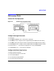
Measure the Power Level Accuracy
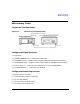
1. Connect the signal generator’s RF OUTPUT through the 6 dB attenuator to the spectrum
analyzer’s RF input.
2. Transfer the power level results for each frequency at
−
15 dBm from the Measured Power
column in Table 3-2 to the Power Meter Reading for
−
15 dBm column in Table 3-3.
3. On the spectrum analyzer, select
Marker Normal Mode and then select the Peak Search
function. This activates the marker and sets it to the signal peak.
4. On the spectrum analyzer, ensure that the marker is at the signal peak and use the
MKR->
menu to set the marker to the reference level. If necessary, select
Peak Search to ensure
that the marker is at the signal peak.
5. With the marker at signal peak, select the
Marker Delta function. This will set the marker to
measure relative amplitude from a reference of 0 dB. If the marker does not read 0 dB,
press
Marker Normal > Peak Search > Marker Delta until the marker reads 0 dB.
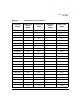
6. Decrease the signal generator amplitude in 10 dB steps as indicated in Table 3-3. With
each 10 dB step, select
Peak Search to ensure that the marker is at the signal peak.
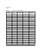
7. Measure the power levels listed in the Power Level Setting (dBm) column of Table 3-3 for
the current frequency, and record the values in the Spectrum Analyzer Marker (dB)
column.
8. Return the spectrum analyzer reference level and the signal generator amplitude to
−
15 dBm. Set the signal generator frequency and the spectrum analyzer’s center frequency
to the next frequency listed in Table 3-3 and repeat the process from step 3.
Continue steps 3–8 until all of the frequencies have been measured and recorded (to the
maximum signal generator frequency).