
Installation guide


Post-Repair Procedures
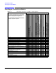
Post-Repair Procedures Matrix
4-5
Table 4-4 Performance Tests for Assemblies A17 through A29, B1, B2, B3, and
the RF Output Connector
Performance Tests
The following performance tests are listed in the
order that they should be performed to minimize
changes in test equipment configurations.
Self Test should be performed each time that any
assembly is repaired or replaced.
Replaced Assembly
A17 Synthesizer (Option 501, 502, 503, 504)
A18 Reference (Option 501, 502, 503, 504)
or A18 Reference (Option 501, 502, 503, 504 with Option 1E5)
or A18 Reference (Option UNJ or Option 506)
A19 Daughterboard
A20 Downconverter (Option 501, 502, 503, 504 with Option 300)
A21 YTO Driver (Option UNJ or Option 506)
A22 Coupler (Option 506)
A23 Motherboard
A23BT1 Battery
A24 Line Module
A25 Rear Panel Board
A26 Rear Panel LVDS Board (Option 1EM)
and A27 Rear Panel SMB Board (Option 1EM)
AT1 Electronic Attenuator (Option 501, 502, 503, 504 or Option UNJ)
or AT1 High-Power Mechanical Attenuator (Option UNB)
and A28 Reverse Power Protection (Option 501, 502, 503, 504 or Option UNJ)
or
AT1 High Power Mechanical Attenuator (Option 506 with Option UNB)
A29 DC Blocking Capacitor (Option 506)
B1 Power Supply Fan
B2 Small Fan
B3 Daughterboard/Card Cage Fan
RF Output Connector
CDMA Adjacent Channel Power
(Not Used with Option UNB or Option 506)
WCDMA Adjacent Channel Power
(Option 400)
Phase Noise and Residual FM
(Manual Test - Option UNJ or Option 506 Only)
XXX
Dual Arbitrary Waveform Generator Check
GSM Loopback BER Check
(Option 300 Only)
X