
Installation guide


Post-Repair Procedures
Post-Repair Procedures Matrix
4-2
Post-Repair Procedures Matrix
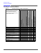
Table 4-1 Performance Tests for Assemblies A1 through A16
Performance Tests
The following performance tests are listed in the
order that they should be performed to minimize
changes in test equipment configurations.
Self Test should be performed each time that any
assembly is repaired or replaced.
Replaced Assembly
A1 Keyboard
A2 Display
A2DS1 Display Backlight
A3 Front Panel Auxilary Board
A4 Inverter
A5 10 GB Hard Drive (Option 005)
A6 Power Supply
A7 Baseband Generator (Option 001)
or A7 Baseband Generator (Option 002)
A9 Digital Demodulator (Option 501, 502, 503, 504 with Option 300)
A10 I/Q Multiplexer (Option 501, 502, 503, 504 or Option UNJ)
or A10 I/Q Multiplexer (Option 506)
A11 Internal Bit Error Rate Analyzer (Option UN7)
A12 CPU
A13 Output (Option 501, 502, 503, 504 or Option UNJ)
or A13 Output (Option UNB)
A14 Extended Frequency Output (Option 506)
A15 Sampler (Option UNJ or Option 506)
A16 Frac-N (Option UNJ or Option 506)
Self Test XXXXXXXXXXXXXXXX
Internal FM Accuracy and Distortion X
Internal AM Accuracy and Distortion XX
Phase Modulation Accuracy and Distortion X
FM Frequency Response X
AM Frequency Response X X
Phase Modulation Frequency Response X
DCFM Frequency Offset Relative to CW X
Residual FM
(Not Used with Option UNJ or Option 506)
X
Harmonic, Subharmonic, and Nonharmonic Spurious
Signals
X X X X X
Power Level Accuracy X X X X
Timebase Aging Rate
(Manual Test - Option UNJ, Option 506, or
Option 1E5 Only)
Digital Modulation Level Accuracy XXX
Internal Digital Modulation Quality
(Option 402 Only)
X X X
Custom I/Q RF Modulation Quality
(Option 402 Only)
XX XX
Pulse Modulation On/Off Ratio X X
Burst Modulation On/Off Ratio XX