
Installation guide


Replaceable Parts
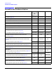
Assemblies and Hardware Options
3-7
Side-SLOT 5
A18 Reference (Option 501, 502, 503, 504) page 3-12
E4400-60512 N/A N/A
or A18 Reference (Option 501, 502, 503, 504 with Option 1E5)
page 3-12
E4400-60513 N/A N/A
or A18 Reference (Option UNJ or Option 506) page 3-12 N/A E4423-60500 E4423-60500
A19 Daughterboard page 3-12 E4400-60719 E4400-60719 E4400-60719
A20 Downconverter (Option 501, 502, 503, 504 with Option 300)
page 3-8
E4400-60544 N/A N/A
A21 YTO Driver (Option UNJ or Option 506) page 3-8 N/A E4423-60510 E4423-60510
A22 Coupler (Option 506) page 3-8 N/A N/A 0950-0098
A23 Motherboard page 3-8 E4400-60504 E4400-60504 E4400-60504
A23BT1 Battery page 3-16 1420-0356 1420-0356 1420-0356
A24 Line Module page 3-15 E4400-60537 E4400-60537 E4400-60537
A25 Rear Panel Board page 3-15 E4400-60506 E4400-60506 E4400-60506
or A26 Rear Panel LVDS Board (Option 1EM)
and A27 Rear Panel SMB Board (Option 1EM) page 3-15
E4400-60524
E4400-60525
E4400-60524
E4400-60525
E4400-60524
E4400-60525
AT1 Electronic Attenuator (Option 501, 502, 503, 504 or
Option UNJ) page 3-8
or AT1 High-Power Mechanical Attenuator (Option UNB)
e
and A28 Reverse Power Protection (Option 501, 502, 503, 504 or
Option UNJ) page 3-8
E4400-60515 E4400-60515 N/A
33322-60014
08648-60025
33322-60014
08648-60025
33322-60014
used
with
A29
0955-1131
A29 DC Blocking Capacitor (Option 506) N/A N/A
B1 Power Supply Fan page 3-8 3160-4133 3160-4133 3160-4133
B2 Small Fan page 3-8 3160-4135 3160-4135 3160-4135
B3 Daughterboard/Card Cage Fan page 3-8 3160-4133 3160-4133 3160-4133
RF Output Connector page 3-14 E4400-60536 E4400-60536 E4400-60536
a. Top-Slot numbers one through five (where one is on the left) refer to the position of an assembly in the top
card-cage of the signal generator when viewed from the top.
b. A11 Internal Bit Error Rate Analyzer (Option UN7) is used with the A9 Digital Demodulator
(Option 501, 502, 503, 504 with Option 300) and A20 Downconverter (Option 501, 502, 503, 504 with
Option 300) for GSM/EDGE basestation loopback BER test capability (it also requires Option 001 or 002 and
Option 402).
c. Side-Slot numbers one through five (where one is on top) refer to the position of an assembly in the right-hand
side card-cage of the signal generator.
d. A13 Output (Option UNB) is used together with A14 Extended Frequency Output (Option 506).
e. AT1 High-Power Mechanical Attenuator (Option UNB) is used together with either an A28 Reverse Power
Protection (Option 501, 502, 503, 504 or Option UNJ) or with an A29 DC Blocking Capacitor (Option 506).
Assembly
Option 501,
502, 503, 504
and
Option 300
Option UNJ Option 506