
Installation guide


Assembly Replacement
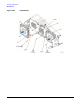
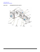
RF Output Connector
2-78
5. Using the T-10 driver, remove the two screws (1) that hold the RF Output Connector and bracket to the
chassis.
6. Using the 9/16” open ended wrench, remove the nut and washer holding the RF Output Connector to the
bracket (2); the bracket does not need to be replaced.
Replacement Procedure
1. Reverse the order of the removal procedure.
2. Torque all RF cables to 9 in-lbs.
3. Perform the post-repair adjustments and performance tests that pertain to this removal procedure.
Figure 2-40 RF Output Connector