
Installation guide


Assembly Replacement
RF Output Connector
2-77
RF Output Connector
Tools Required
• 5/16” open ended wrench
• 9/16” open ended wrench
• T-10 driver
Removal Procedure
Refer to Figure 2-40 and Figure 3-28 for this procedure.
1. Disconnect the power cord.
2. Remove the outer and top inner cover. Refer to “Outer and Inner Instrument Covers” on page 2-4.
3. Remove the front panel. Refer to “Front Panel” on page 2-6.
4. On signal generators:
• with Option 501, 502, 503, 504 or Option UNJ, using the 5/16” open ended wrench:
— disconnect W9 from the RF Output Connector
• with Option 506, using the 5/16” open ended wrench:
— disconnect W59 from the A29 DC Blocking Capacitor (Option 506)
— disconnect A29 DC Blocking Capacitor (Option 506) from W60
— disconnect W60 from the RF Output Connector
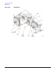
5. Using the T-10 driver, remove the two screws (1) that hold the RF Output Connector and bracket (2) to the
chassis; they are replaced as one assembly.
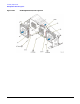
Removal Procedure for Option 1EM
Refer to Figure 2-41 for this procedure.
1. Disconnect the power cord.
2. Remove the outer and top inner cover. Refer to “Outer and Inner Instrument Covers” on page 2-4.
3. Remove the rear-panel chasis-support bracket. (From a top view, this covers the RF Output Connector.)
4. On signal generators:
• with Option 501, 502, 503, 504 or Option UNJ, using the 5/16” open ended wrench:
— disconnect W85 from the RF Output Connector
• with Option 506, using the 5/16” open ended wrench:
— disconnect W91 from the A29 DC Blocking Capacitor (Option 506)
— disconnect A29 DC Blocking Capacitor (Option 506) from the RF Output Connector