
Installation guide


Assembly Replacement
A29 DC Blocking Capacitor (Option 506)
2-69
A29 DC Blocking Capacitor (Option 506)
Tools Required
• 5/16” open ended wrench
Removal Procedure
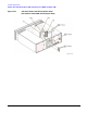
Refer to Figure 2-35 for this procedure.
1. Disconnect the power cord.
2. Remove the outer and top inner cover. Refer to “Outer and Inner Instrument Covers” on page 2-4.
3. Remove the front panel. Refer to “Front Panel” on page 2-6.
4. Using the 5/16” open ended wrench, disconnect W59 from the A29 DC Blocking Capacitor (Option 506).
5. Using the 5/16” open ended wrench, disconnect A29 DC Blocking Capacitor (Option 506) from W60.
6. Remove the A29 DC Blocking Capacitor (Option 506).
Removal Procedure for Option 1EM
Refer to Figure 2-36 for this procedure.
1. Disconnect the power cord.
2. Remove the outer and top inner cover. Refer to “Outer and Inner Instrument Covers” on page 2-4.
3. Using the 5/16” open ended wrench, disconnect W91 from the A29 DC Blocking Capacitor (Option 506).
4. Using the 5/16” open ended wrench, disconnect A29 DC Blocking Capacitor (Option 506) from the
RF Output connector.
5. Remove the A29 DC Blocking Capacitor (Option 506).
Replacement Procedure
1. Reverse the order of the removal procedure.
2. Torque all RF cables to 9 in-lbs.
3. Perform the post-repair adjustments and performance tests that pertain to this removal procedure.