
Installation guide


Assembly Replacement
AT1 Electronic Attenuator (Option 501, 502, 503, 504 or Option UNJ)
2-67
AT1 Electronic Attenuator (Option 501, 502, 503, 504 or Option UNJ)
Tools Required
• T-10 driver
• 5/16” open ended wrench
Removal Procedure
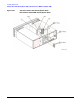
Refer to Figure 2-34 for this procedure.
1. Disconnect the power cord.
2. Remove the outer and inner covers. Refer to “Outer and Inner Instrument Covers” on page 2-4.
3. Using the 5/16” open ended wrench:
• disconnect W43
• disconnect W9
On signal generators with Option 1EM, disconnect W85. (Refer to “Option 501, 502, 503, 504 - Option
1EM Semi-Rigid Cables includes the AT1 Electronic Attenuator (Option 501, 502, 503, 504 or
Option UNJ) or the AT1 High-Power Mechanical Attenuator (Option UNB) with the A28 Reverse
Power Protection (Option 501, 502, 503, 504 or Option UNJ)” on page 3-35.)
4. Using the T-10 driver, remove the two screws (1) that attach the AT1 Electronic Attenuator
(Option 501, 502, 503, 504 or Option UNJ) to the chassis.
5. Disconnect W40 from A23J25.
6. Remove the AT1 Electronic Attenuator (Option 501, 502, 503, 504 or Option UNJ) by leaning it forward
and guiding out the hinged tabs located at the bottom of the bracket.
7. Using the T-10 driver, remove the three screws that attach the sheet metal to the AT1 Electronic
Attenuator (Option 501, 502, 503, 504 or Option UNJ).
Replacement Procedure
1. Reverse the order of the removal procedure.
2. Torque all T-10 screws to 9 in-lbs.
3. Torque all RF connectors to 8 in-lbs.
4. Perform the post-repair adjustments and performance tests that pertain to this removal procedure.