
Installation guide


Assembly Replacement
A26 Rear Panel LVDS Board (Option 1EM) and A27 Rear Panel SMB Board (Option 1EM)
2-61
A26 Rear Panel LVDS Board (Option 1EM)
and A27 Rear Panel SMB Board (Option 1EM)
Tools Required
• T-10 driver
• 5/8” hex-nut driver
• 3/16” hex-nut driver
• 9/16” open-ended wrench
• 5 mm nut driver
• needle-nose pliers
Removal Procedure
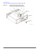
Refer to Figure 2-31 for this procedure.
1. Disconnect the power cord.
2. Remove the outer cover. Refer to “Outer and Inner Instrument Covers” on page 2-4.
3. Disconnect all cables connected to the A26 Rear Panel LVDS Board (Option 1EM)
and A27 Rear Panel SMB Board (Option 1EM).
4. Using the 9/16” open-ended wrench, remove the nuts (1)
on the A27 Rear Panel SMB Board (Option 1EM).
5. Using a small phillips screw driver, remove the two screws (2)
from the A26 Rear Panel LVDS Board (Option 1EM).
6. Using the 5 mm nut driver, remove the shoulder screws (3)
from the A26 Rear Panel LVDS Board (Option 1EM).
7. Remove the A26 Rear Panel LVDS Board (Option 1EM)
and A27 Rear Panel SMB Board (Option 1EM) from the chassis.
Replacement Procedure
1. Reverse the order of the removal procedure.
2. Torque the GPIB hex screw to 9 in-lb.
3. Torque the RS-232 hex screw to 6 in-lb.
4. Torque all T-10 screws to 9 in-lbs.
5. Torque all BNC nuts to 21 in-lbs.
6. Perform the post-repair adjustments and performance tests that pertain to this removal procedure.