
Installation guide


Assembly Replacement
A25 Rear Panel Board
2-59
A25 Rear Panel Board
Tools Required
• T-10 driver
• 3/16” hex-nut driver
• 9/16” open-ended wrench
• 5 mm nut driver
• small phillips screw driver
Removal Procedure
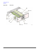
Refer to Figure 2-30 for this procedure.
1. Disconnect the power cord.
2. Remove the outer cover. Refer to “Outer and Inner Instrument Covers” on page 2-4.
3. Disconnect W10 from the A25 Rear Panel Board.
4. Disconnect W32 from the A25 Rear Panel Board.
5. Using the 9/16” open-ended wrench, remove the nuts on the EVENT 1, EVENT 2, PATT TRIG IN,
BURST GATE IN, connectors (1).
6. Using the 5 mm nut driver, remove the shoulder nuts and washers from the AUX I/O connector (2).
7. Using a small phillips screw driver, remove the two screws from the DIG I/Q I/O connector (3).
8. Remove the A25 Rear Panel Board from the chassis.
Replacement Procedure
1. Reverse the order of the removal procedure.
2. Torque all T-10 screws to 9 in-lbs.
3. Torque all BNC nuts to 21 in-lbs.
4. Perform the post-repair adjustments and performance tests that pertain to this removal procedure.