
Installation guide


Assembly Replacement
Rear Panel
2-57
Rear Panel
Tools Required
• T-10 driver
• 5/8” hex-nut driver
• 9/32” nut driver
• 3/16” nut driver
• needle-nose pliers
Removal Procedure
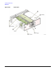
Refer to Figure 2-29 for this procedure.
1. Disconnect the power cord.
2. Remove the outer cover. Refer to “Outer and Inner Instrument Covers” on page 2-4.
3. Disconnect all cables connected to the Rear Panel.
4. Using the 9/32” nut driver, remove the nuts on the GPIB connector (1).
5. Using the 3/16” nut driver, remove the nuts on the RS-232 connector (2).
6. Using the 5/8” hex-nut driver, remove the nuts and washers from the 10 MHz OUT, 10 MHz IN, TRIG IN,
and TRIG OUT (3).
NOTE Do not remove the screw that secures the chain and cap for the COH CARRIER.
7. Using the T-10 driver, remove the eight screws (4) from the Rear Panel.
8. Using the T-10 driver, remove the 13 screws (5) from the A6 Power Supply’s shielding.
9. Disconnect the A24W1 (6) from the A6 Power Supply.
10.Remove the Rear Panel from the chassis.
Replacement Procedure
1. Reverse the order of the removal procedure.
2. Torque the GPIB hex screw to 9 in-lb.
3. Torque the RS-232 hex screw to 6 in-lb.
4. Torque all T-10 screws to 9 in-lbs.
5. Torque all BNC nuts to 21 in-lbs.
6. Perform the post-repair adjustments and performance tests that pertain to this removal procedure.