
Installation guide


Assembly Replacement
A24 Line Module
2-56
A24 Line Module
Tools Required
• T-10 driver
Removal Procedure
Refer to Figure 2-28 for this procedure.
1. Disconnect the power cord.
2. Remove the outer cover. Refer to “Outer and Inner Instrument Covers” on page 2-4.
3. Remove the Rear Panel. Refer to “Rear Panel” on page 2-57.
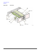
4. Using a T-10 driver, remove the screw (2) that secures the A24 Line Module (1) to the Rear Panel.
5. Remove the A24 by pulling the metal tab at the top of the line module, and at the same time, pushing up
at the bottom of the line module to release it from the rear panel.
Replacement Procedure
1. Reverse the order of the removal procedure.
2. Torque all T-10 screws to 9 in-lbs.
3. Perform the post-repair adjustments and performance tests that pertain to this removal procedure.
Figure 2-28 A24 Line Module