
Installation guide


Assembly Replacement
A23 Motherboard
2-52
A23 Motherboard
Tools Required
• T-10 driver
• 5/8” open-ended wrench
• 3/16” nut driver
• 9/32” nut driver
• needle-nose pliers
Removal Procedure
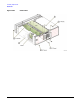
Refer to Figure 2-26 for this procedure.
1. Disconnect the power cord.
2. Remove the outer and top inner covers. Refer to “Outer and Inner Instrument Covers” on page 2-4.
3. Remove the A6 Power Supply. Refer to “A6 Power Supply” on page 2-20.
4. Remove all of the assembly boards inserted into the A23 Motherboard.
For cable removal, refer to “A12 CPU” on page 2-30.
5. Remove the following cables from the A23 Motherboard:
• W27 ribbon cable from A23J34 (Option UNJ)
• W63 ribbon cable from A23J26 (Option 300)
• W40 ribbon cable from A23J25 (AT1 Electronic Attenuator (Option 501, 502, 503, 504 or Option UNJ)
• W57 ribbon cable from A23J25 (AT1 High-Power Mechanical Attenuator (Option UNB)
• W32 wire cable from A23J36
• W31 from A23J20, using the needle-nose pliers
• B1W1 fan cable from A23J33
• B2W1 fan cable from A23J27
• B3W1 fan cable from A23J29
6. Using the 3/16” nut driver, remove the shoulder nuts (2) and washers (1) on the RS-232 connector.
7. Using the 5/8” open-ended wrench, remove the nuts (3) and washers (4) from the 10 MHz OUT,
10 MHz IN, TRIG IN, and TRIG OUT.
8. Using the 9/32” nut driver, remove the shoulder nuts (5) and washers (6) on the GPIB connector.
9. Using the T-10 driver, remove the eight screws (7) on the Rear Panel (8).
10.Using the T-10 driver, remove the five screws (9) that hold the A23 Motherboard to the chassis.
11.Using the T-10 driver, remove the four screws (10) that hold the bottom rib (11) to the A23 Motherboard.
12.Gently pry out the Rear Panel, guide out the BNCs, and remove the A23 Motherboard from the chassis.