
Installation guide


Assembly Replacement
A21 YTO Driver (Option UNJ or Option 506) and A22 Coupler (Option 506)
2-51
Replacement Procedure
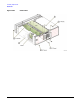
NOTE Make sure that the tabs on the A21 YTO Driver (Option UNJ or Option 506) hook bracket line
up with the slots in the chassis.
1. Reverse the order of the removal procedure.
2. Torque all T-10 screws to 9 in-lbs.
3. Torque all RF connectors to 9 in-lbs.
4. Perform the post-repair adjustments and performance tests that pertain to this removal procedure.
Figure 2-25 A21 YTO Driver (Option UNJ or Option 506)