
Installation guide


Assembly Replacement
A21 YTO Driver (Option UNJ or Option 506) and A22 Coupler (Option 506)
2-50
A21 YTO Driver (Option UNJ or Option 506)
and A22 Coupler (Option 506)
Tools Required
• T-10 driver
• 5/16” open ended wrench
• needle-nose pliers
Removal Procedure
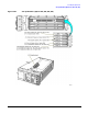
Refer to Figure 2-25 for this procedure.
1. Disconnect the power cord.
2. Remove the outer and inner covers. Refer to “Outer and Inner Instrument Covers” on page 2-4.
3. Disconnect the W27 ribbon cable from the A21 YTO Driver (Option UNJ or Option 506).
4. Using needle-nose pliers, disconnect the following cables:
• W28 from A21J3
• W29 from A21J4
5. Using the 5/16” open ended wrench, disconnect the following RF cables
from the A21 YTO Driver (Option UNJ or Option 506):
•W37
•W38
• On signal generators with Option 506:
—disconnect W56
— if removing the A22 Coupler (Option 506):
— disconnect W55
— disconnect W54
— remove the two screws (3) holding the A22 Coupler (Option 506)
to the A21 YTO Driver (Option UNJ or Option 506)
6. Using the T-10 driver, remove the two screws (1) from the hook bracket that are holding
the A21 YTO Driver (Option UNJ or Option 506) to the chassis.
7. Tilt the hook bracket away from the chassis and slide out the tabs from the slots.
The hook bracket has two hinged tabs at the bottom that fit into slots in the signal generator’s chassis.
8. Using the T-10 driver, remove the four screws (2) that hold the hook bracket
to the A21 YTO Driver (Option UNJ or Option 506).