
Installation guide


Assembly Replacement
A19 Daughterboard
2-44
A19 Daughterboard
Tools Required
• T-10 driver
Removal Procedure
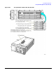
Refer to Figure 2-22 for this procedure and to the connector/cable diagram located on the card cage.
1. Disconnect the power cord.
2. Remove the outer and inner-side covers. Refer to “Outer and Inner Instrument Covers” on page 2-4.
NOTE It is recommended to label the assembly boards before you remove them from the card cage for
easy installation.
3. Remove all of the board assemblies from the side-card cage (located on the left side of the signal generator)
by lifting the retention levers and disconnecting the assembly boards from the A19 Daughterboard.
4. Using the T-10 driver, remove the five screws that attach the A19 Daughterboard to the signal generator’s
chassis.
5. Remove the A19 Daughterboard from the card cage.
Replacement Procedure
1. Reverse the order of the removal procedure.
2. Torque all T-10 screws to 9 in-lbs.
3. Perform the post-repair adjustments and performance tests that pertain to this removal procedure.