
Installation guide


Assembly Replacement
A13 Output
2-32
A13 Output
NOTE This procedure applies to both the A13 Output (Option 501, 502, 503, 504 or Option UNJ)
and the A13 Output (Option UNB).
Tools Required
•none
Removal Procedure
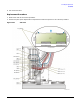
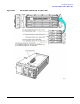
Refer to Figure 2-16 for this procedure and to the connector/cable diagram located on the card cage.
1. Disconnect the power cord.
2. Remove the outer and inner-side covers. Refer to “Outer and Inner Instrument Covers” on page 2-4.
3. Locate Side-SLOT 1, lift the retention levers, and disconnect the A13 Output from
the A19 Daughterboard.
4. Slide out the A13 Output.
Replacement Procedure
1. Reverse the order of the removal procedure.
2. Perform the post-repair adjustments and performance tests that pertain to this removal procedure.