
Installation guide


Troubleshooting
Block Descriptions for Option UNJ and Option 506
1-138
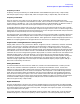
RF Path Block Description for Option UNJ or Option 506
Overview
The RF Path for signal generators with Option UNJ and Option 506 is made from portions of the following:
• A18 Reference (Option UNJ or Option 506)
• A15 Sampler (Option UNJ or Option 506)
• A16 Frac-N (Option UNJ or Option 506)
• A21 YTO Driver (Option UNJ or Option 506)
• A13 Output (Option UNJ)
or A13 Output (Option UNB)
• AT1 Electronic Attenuator (Option 501, 502, 503, 504 or Option UNJ)
with A28 Reverse Power Protection (Option 501, 502, 503, 504 or Option UNJ)
or AT1 High-Power Mechanical Attenuator (Option UNB)
with A29 DC Blocking Capacitor (Option 506)
The RF Path consists of a portion of the A16 Frac-N, A21 YTO Driver, and the A13 Output. Frequency
generation is accomplished with a YIG Oscillator (YO) on the A21 YTO Driver. The YO is tuned by the
A16 Frac-N and the A15 Sampler. The YO signal is then routed through the A16 Frac-N to the A13 Output.
The A13 Output contains the Automatic Level Control (ALC) loop for maintaining leveled power. For
Option 506, an additional output board, A14 Extended Frequency Output, is added to control power for
frequencies greater than 4 GHz to 6 GHz.
For RF frequencies below 250 MHz, a heterodyne mixer is switched into the RF path. The RF signal is mixed
with a 1 GHz LO, provided by the A18 Reference, to produce the final 100 kHz to < 250 MHz output;
specifications apply to frequencies ≥ 250 kHz.
AM, Pulse/Burst, and I/Q baseband signals modulate the RF on the A13 Output. The AM and Pulse
modulation originate on the A17 Reference board. While the I/Q and Burst modulation originate on the A7
Baseband Generator. The I/Q signal is routed via the A10 I/Q Multiplexer to the A13 Output. The Burst
modulation signal is routed via the A18 Reference to the A13 Output.
The RF signal leaving the A13 Output is then routed through an electronic attenuator. The attenuator also
includes a Reverse Power Protection (RPP) circuit to prevent damage to the signal generator. Options UNB
replaces the electronic attenuator with a mechanical attenuator. Option 506 doesn't include an RPP circuit,
but instead uses the A29 DC Blocking Capacitor (Option 506).
The signal generator’s maximum frequency and power are dependent on its options.
A21 YTO Driver (Option UNJ or Option 506)
The operating frequency of the YO on the A21 YTO Driver is from 4 to 8 GHz. YO tuning is accomplished by
varying the current through the main coil. This causes the coil's magnetic field to change, which tunes the YO
resonant frequency. When FM is enabled, both the FM coil and main coil are used to tune the YO. The
A15 Sampler and A16 Frac-N tune the main coil and FM coil respectively. For more details on the tuning of
the YO, refer to “Frequency Synthesis Block Description for Option UNJ and Option 506” on page 1-135.
The YO output is then split and routed to the A16 Frac-N and the A15 Sampler. The A15 Sampler path is part
of the Frequency Synthesis Block.