
Installation guide


Troubleshooting
Troubleshooting Pulse Modulation and LF Out
1-108
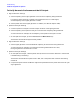
To Verify the Pulse Waveform at the A19 Daughterboard (All Options)
1. Turn power off to the signal generator.
2. Remove the A13 Output.
3. Install a ribbon cable extender
1
into J12 on the A19 Daughterboard.
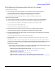
J12 is a 30-pin connector and the ribbon cable extender has only 20 pins. Align the ribbon cable extender
with the pins on the left side of J12. When the ribbon cable extender is properly installed, you will see
two rows (5 pins each) on the right-side of the ribbon cable extender.
Figure 1-25
1. The ribbon cable extender needs to be assembled by the user. It consists of two connector plugs
(part number 1252-1010) and approximately eight inches of ribbon cable (part number 8120-2226).
The ribbon cable contains 26 wires; six of these wires need to be stripped off before being connected
to the plugs.