
User`s guide

24 User’s Guide
Signal Studio for WiMAX E4438C Option H13
WiMAX Project Parameters
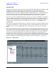
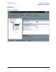
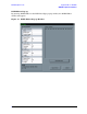
Frame View
The Frame View shows a list of bursts for both Downlink and Uplink. It is possible to add
or delete various types of bursts. You can also change the order of the bursts by
highlighting a burst and then clicking the “Move Up” or “Move Down” button. The
maximum number of bursts is 100 per downlink or uplink. There is a “Check Parameters”
button on the top of the view for checking all parameters' validity before a waveform
generation. The results are shown in the Status Bar at the bottom of the window.
Note that in general, the ESG will simulate either a base station (downlink) or subscriber
station (uplink) transmitter, so the waveform will only consist of a downlink or uplink
signal, not both at the same time. The Frame View shown below is only to demonstrate the
various frame components that can be added. It does not show a valid WiMAX signal
configuration.
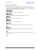
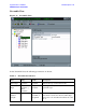
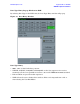
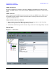
Each burst has specific parameters that are shown on separate view pages. Display burst
parameters by clicking on a burst in the Tree View, or double-clicking to the left of the “#”
column (where the arrow is displayed for the selected burst) in the row for the desired
burst.
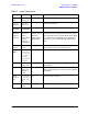
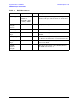
The tables summarize the key characteristics for each burst. The amplitude column shows
the average power level of the preamble compared to the FCH/data burst portion of each
subframe. Note that the ESG amplitude setting matches the power level of the FCH/data
burst portion and the preamble power level is always 3 dB higher as specified in the
standard. If the frame contains only a preamble, then the ESG amplitude setting matches
the power level of the preamble. The item used for the amplitude reference is identified in
the Project View in the "Signal Generator Settings" section, see Figure 14 on page 22.
Figure 12 Frame View